


13
Magtrol Hysteresis Dynamometers
Chapter 1 – Introduction
GENERAL
INFORMA
TION
www.magtrol.com
DATASHEET
Page 4 / 16
© 2016 MAGTROL | Due to continual product development, Magtrol reserves the right to modify specifications without forewarning.
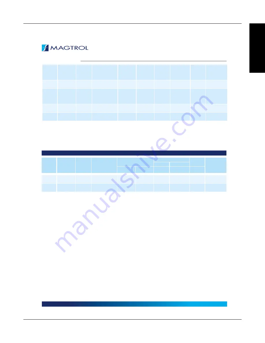
HD
SERIES
HD-800
5N
14.00
0.10 N·m
4.43 × 10
-3
6.01 × 10
-3
2,800
1,800
12,000
Compressed
Air
c)
(13 CFM @
10 PSI)
HD-810
5N
14.00
0.10 N·m
4.43 × 10
-3
6.01 × 10
-3
3,500
3,000
12,000
Blower
(included)
HD-805
5N
28.00
0.14 N·m
8.81 × 10
-3
1.19 × 10
-2
5,300
3,000
12,000
Compressed
Air
c)
(15 CFM @
14 PSI)
HD-815
5N
28.00
0.14 N·m
8.81 × 10
-3
1.19 × 10
-2
7,000
6,000
12,000
Blower
(included)
HD-825
5N
56.50
0.22 N·m
1.85 × 10
-2
2.51 × 10
-2
14,000
12,000
8,000
Blower
(included)
a)
All -5N(A) dynamometers are 5 Volt Output. Contact Magtrol for 6N (English), 7N (Metric) and 8N (SI) Specifications.
b)
Note: Operating at the continuous power rating for periods of up to 4 hours is acceptable. However, operating for extended periods at high temperatures will
result in premature component and bearing failure. Limiting the length of the cycle and the component temperatures will guard against premature failure. Where
continuous duty is desired for longer time intervals, component temperatures should be maintained less than 100°C; monitoring the outside brake surface
temperature is a sufficient reference.
c)
Requires air cooling provided by user. Regulator and filter package is provided as standard equipment on these units.
ED ENGINE DYNAMOMETER RATINGS
MODEL
TORQUE
MEASURE
UNIT CODE
a)
MAXIMUM
TORQUE
RANGE
DRAG TORQUE
DE-ENERGIZED AT
1,000 RPM
NOMINAL INPUT INERTIA
MAX. POWER RATINGS
MAXIMUM
SPEED
c)
BRAKE
COOLING
METHOD
5 MINUTE CONTINUOUS
b)
lb·ft·s
2
kg·m
2
W
W
RPM
N·m
ED-715
5N
6.20
0.035 N·m
1.27 × 10
-3
1.72 × 10
-3
3,400
3,000
25,000
Blower
(included)
ED-815
5N
28.0
0.14 N·m
9.61 × 10
-3
1.30 × 10
-2
7,000
6,000
12,000
Blower
(included)
a)
All -5N(A) dynamometers are 5 Volt Output. Contact Magtrol for 6N (English), 7N (Metric) and 8N (SI) Specifications.
b)
Note: Operating at the continuous power rating for periods of up to 4 hours is acceptable. However, operating for extended periods at high temperatures will
result in premature component and bearing failure. Limiting the length of the cycle and the component temperatures will guard against premature failure. Where
continuous duty is desired for longer time intervals, component temperatures should be maintained less than 100°C; monitoring the outside brake surface
temperature is a sufficient reference.
c)
The maximum speed will depend on what type of keyway (if any) is used on the shaft. Unless specified, the dynamometer shaft will be made without a keyway.
SPECIFICATIONS