background image

2 - Installation 

tDynamo| Three-way Secure Card Reader Authenticator | Installation and Operation Manual 


Page 22 of 39 (

D998200257-20

2.3


Mounting tDynamo 

2.3.1


About Mounting 

tDynamo’s design provides two mount points: A 

Lanyard Mount Point

 and a 

Locking Mount Point


(see section 

1.8 About tDynamo Components

).  The two mount points can be used in various 

combinations: 


The lanyard mount point can be used to hang the device for convenient hanging storage and/or 
handling in handheld sales solutions. 


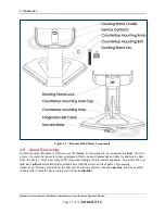
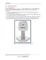
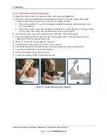
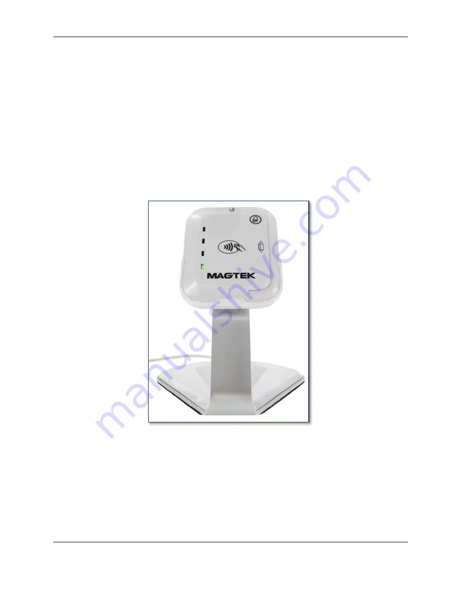
The locking mount point can be used with the optional docking stand (shown i

Figure 2-2

) mounted 

to a countertop for stability in stationary sales solutions. 


The locking mount point can also be used with custom brackets to mount to other devices or surfaces. 


The docking stand can also be used in unlocked mode, and optionally combined with the lanyard 
mount point, for quick grab-and-go and convenient drop-in charging between handheld sessions. 


Figure 2-2 - tDynamo Installed On Optional Docking Stand 


Summary of Contents for tDynamo

Page 1: ...ach CA 90740 I Phone 562 546 6400 I Technical Support 888 624 8350 www magtek com tDynamo Three way Secure Card Reader Authenticator Installation and Operation Manual August 2018 Document Number D9982...

Page 2: ...iers containing ANSI are registered trademarks service marks and accreditation marks of the American National Standards Institute ANSI EMV is a registered trademark in the U S and other countries and...

Page 3: ...7 20 Table 0 1 Revisions Rev Number Date Notes 10 May 18 2018 Initial Release 20 Aug 17 2018 Add supporting information about optional docking stand Retrofit new Sleep Mode throughout Update 3 2 About...

Page 4: ...any liability or warranty for goods resold in other than MagTek s original packages and for goods modified altered or treated without authorization by MagTek Service may be obtained by delivering the...

Page 5: ...ED EXCEPT AS MAY BE STATED IN THIS AGREEMENT AND MAGTEK DISCLAIMS ANY IMPLIED WARRANTY INCLUDING WITHOUT LIMITATION ANY IMPLIED WARRANTY OF MERCHANTABILITY OR FITNESS FOR A PARTICULAR PURPOSE MAGTEK S...

Page 6: ...g the equipment off and on the user is encouraged to try to correct the interference by one or more of the following measures Reorient or relocate the receiving antenna Increase the separation between...

Page 7: ...2 1 10 About Solution Planning 13 2 Installation 14 2 1 About Host Software 14 2 2 Connecting to a Host 15 2 2 1 About Connecting tDynamo to a Host 15 2 2 2 How to Connect tDynamo to a Host Computer v...

Page 8: ...to Force Reset 30 3 5 Card Reading 31 3 5 1 About Reading Cards 31 3 5 2 How to Swipe Magnetic Stripe Cards 32 3 5 3 How to Insert Contact Chip Cards 33 3 5 4 How to Tap Contactless Cards Devices 34...

Page 9: ...ry standard USB C connector or docking stand contacts Allows over 200 card swipes or insertions over 8 hours between charges 1 2 Fixed or Mobile tDynamo allows you to easily go between a fixed platfor...

Page 10: ...tegration MagTek understands the value of easy to use and well documented Software Development Kits SDKs technical documentation APIs and sample code MagTek SDKs have no royalties or maintenance fees...

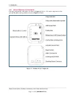
Page 11: ...lation and Operation Manual Page 11 of 39 D998200257 20 1 8 About tDynamo Components The major components of tDynamo are shown in Figure 1 1 below The major components of the optional tDynamo docking...

Page 12: ...to a host which is a piece of general purpose electronic equipment which can send commands and data to and receive data from the device Host types include PC computers laptops tablets and smartphones...

Page 13: ...can be reconfigured afterward Determine how tDynamo should be configured and specify that when you order devices For example although tDynamo comes with a factory default Bluetooth LE passkey it is a...

Page 14: ...vice and mounting the device 2 1 About Host Software In any solution tDynamo is connected to a host which must have software installed that knows how to communicate with the device and which is capabl...

Page 15: ...o a host computer using the optional docking stand see section 2 3 Mounting tDynamo To connect tDynamo to a host computer using the USB C Connector follow these steps 1 Make sure tDynamo is configured...

Page 16: ...n download a test tool from the App Store called MagTek Test published by MagTek Inc 4 Make sure tDynamo is powered on is not in sleep mode and that its battery is adequately charged see section 3 4 1...

Page 17: ...ge asking for a code enter the configured passkey or the default 000000 9 The app reports the device is now Connected and the device indicates it is in Connected mode see section 3 2 About the Status...

Page 18: ...conserve power 11 Remember to change the default passkey See the tDynamo Programmer s Manual documentation for details To unpair from the device follow these steps 1 On the iOS host launch the Settin...

Page 19: ...le Play store called MagTek Test published by MagTek Inc 4 Make sure tDynamo is powered on is not in sleep mode and that its battery is adequately charged see section 3 4 1 About Power for instruction...

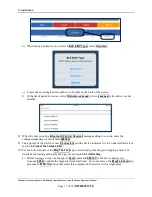
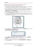
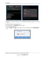
Page 20: ...k Test app to connect to the device and to test swiping inserting and tapping a card For details about reading each payment type see section 3 5 Card Reading a After connecting to the device the app r...

Page 21: ...Remember to change the default passkey See the tDynamo Programmer s Manual documents for details To unpair from the device follow these steps 1 Locate the device in the Bluetooth configuration page 2...

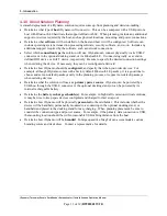
Page 22: ...ed to hang the device for convenient hanging storage and or handling in handheld sales solutions The locking mount point can be used with the optional docking stand shown in Figure 2 2 mounted to a co...

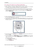
Page 23: ...docked for cardholder use placing the stand so it hangs slightly over the edge of the surface may provide the least obstructed swipe path 2 Open the protective cap over the mounting hole on the base o...

Page 24: ...ently Dock tDynamo Do not leave the round key installed in the docking stand The key is designed to be removed to deter unauthorized removal of the device To permanently attach the device to the docki...

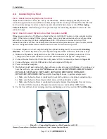
Page 25: ...onnected to USB power it will move from Discoverable Mode to Sleep Mode automatically when its configurable timeout period has passed If the device is configured to transmit data over USB and is conne...

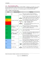
Page 26: ...arge immediately device can not process transactions Amber Red Green LEDs 4 3 2 1 Light In Sequence The device has read a contactless tap and the cardholder can safely remove the card or device from t...

Page 27: ...ion Manual Page 27 of 39 D998200257 20 Color Flashing Pattern Meaning Red Steady On The device is in Sleep Mode The General Status LED is solid red and LED 3 is solid green Red Steady On An operator i...

Page 28: ...device The device sounds one short beep on startup to test the beeper and indicate the device is powered on The device sounds one short beep after it has successfully read a contactless tap and the c...

Page 29: ...solid green When the device is already in Sleep Mode after a further period of inactivity the device powers off completely and turns off all LEDs The host can set the device s Sleep Mode and Power Of...

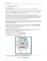
Page 30: ...uire a USB connection that can provide at least 500mA 5V A full recharge cycle for a completely drained battery takes approximately 4 5 hours To charge the device using a USB C cable connect it to a U...

Page 31: ...either from its rechargeable battery or from one of the USB connections and is awake and powered on see section 3 4 4 How to Power On Wake Up from Sleep Mode Power Off and section 3 2 About the Statu...

Page 32: ...Magnetic Stripe Cards Cardholders should swipe magnetic stripe cards in the MSR swipe path indicated by the bidirectional MSR swipe symbol shown on the device s face The magnetic stripe must face towa...

Page 33: ...Operation Manual Page 33 of 39 D998200257 20 3 5 3 How to Insert Contact Chip Cards Cardholders should insert chip cards into the chip card slot indicated by the chip card orientation symbol shown on...

Page 34: ...device s General Status LED lights solid green indicating it is ready for a tap 3 Tap the card or electronic payment device on the contactless landing zone indicated by the EMVCo Contactless Indicator...

Page 35: ...double sided cleaning card 96700004 is designed to clean the magnetic read head in the MSR swipe path and the contact pins inside all chip card contact readers Keeping both of these components clean i...

Page 36: ...able images such as exe or DLL files In addition to the SDK API libraries custom software on any operating system can communicate directly with the device using native USB libraries and protocols If y...

Page 37: ...racteristics Dimensions L x W x H 3 94 in x 3 25 in x 0 61 in 100 mm x 82 5 mm x 15 5 mm Weight Handheld 3 oz 82 g With docking stand 10 oz 285 g Supported Mounting Options Handheld Lanyard Countertop...

Page 38: ...Time Powered Off Up to 2 years time from 60 charge to 0 charge Battery Time Idle Up to 10 hours Battery Time Sleep Mode Up to 60 hours More than 2 days Battery Time Transactions Over an 8 hour shift w...

Page 39: ...mental Tolerance Operating Temperature 32 F to 113 F 0 C to 45 C Operating Relative Humidity 10 to 90 without condensation Storage Temperature 14 F to 113 F 10 C to 45 C Storage Relative Humidity 10 t...

Reviews: