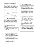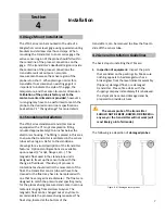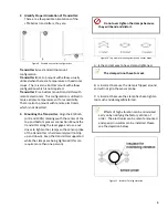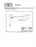
7.1 Menu Structure Continued…
Description
Select PV:
This menu allows the user to select the
measurement that controls the transmitter’s
current output (mA).
This menu only appears if the interface
(2 floats) option is provided.
Select Alarm:
The following alarm settings can be chosen:
“FailHigh” = 21.00mA
“FailLow” = 3.50mA
“HoldOut” = holds last good reading until
transmitter recovers.
Change Range:
This menu allows the user to change the measuring
range or span. Enter the menu by changing the
“No” to a “Yes” and press enter.
- Select Lower Range Value (LRV):
This is the 4.00mA (0.00%) point on the senor. This
value should only be incremented. For example if
the value is changed from “0.00in” to “3.00in” the
4.00mA point will shift 3.00 inches higher than the
original point. It is recommended to leave this at
0.00 most of the time unless a special circumstance
arises. Press enter to go the next screen.
- Select Upper Range Value (URV):
This is the 20.00mA (100.00%) point on the sensor.
This value should only be decremented. Changing
this parameter will change the measuring range or
span of the transmitter.
Select Damping:
This parameter is used to slow down the reaction of
the instrument in order to ignore or average out
any agitation on the process surface that may be
causing an unsteady output. The units are fixed in
seconds and values can be from 1 to 26 seconds.
LCD Menu (examples)
S e l
P V
L e v e l
S e l A l
a r m
F a i l
H i
g h
C h g R n g e ?
N o
S e l
L R V
0 . 0 0 i
n
S e l
U R V
2 0 . 0 0 i
n
S e l
D a m p
1
s
19


