background image

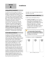
4. Remote Mount Electronics Option.

  Due to 

process temperature, vibration or accessibility 

the housing/electronics of the LTM transmitter 

can be remote mounted as far as 25 ft.  The 

housing/electronics are supplied with a pipe-

mount bracket that can be mounted most 

nearby posts or pipes with hose clamps.  The 

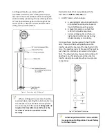
drawing below depicts a gage mounted 

transmitter in the top mount remote electronics 

configuration.

Figure 12.  Gage mount transmitter in the top mount remote 

electronics configuration.

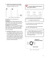
NEVER install the sensor probe inside an 

insulation blanket that may be around the 

level gage.

  This will overheat the sensor probe 

and cause failure.

NEVER

bend, bow or cause a kink in the 

sensor probe, this will damage the instrument 

and void the warranty.  Do not attempt to 

straighten the sensor probe, this will not help 

the instrument work.  If the shipment arrives 

damaged please file a claim with the shipping 

company and contact the factory to arrange for 

a replacement.

There are a variety of ways to install a 

standalone transmitters (i.e. crane, lift, etc…), 

the basic rule to remember when installing an 

LTM transmitter is 

DO NOT DAMAGE the 

sensor probe

, this will void the warranty.  If 

damage is suspected please contact the factory 

and be prepared to provide pictures.

In 

REMOTE MOUNT

electronic options 

please support the sensor probe at the 

elbow/condulet and then every 3 feet 

(depending on length of cable).  Support at 

every 2 feet may be required if explosion proof 

conduit is utilized by the end user.

9

Summary of Contents for LTM-250

Page 1: ...as 77584 Phone 281 488 0788 Fax 281 488 7080 E mail magtech isemagtech com Website www isemagtech com LTM Series Models LTM 250 and LTM 350 Magnetostrictive Level Transmitters Instructions Operation M...

Page 2: ...on 7 4 0 Gage Mount Installation 7 4 1 Standalone Installation 7 4 2 General Installation Guidelines 7 4 3 Insulation against extreme heat cold 10 Section 5 Field Wiring 11 5 0 Recommended Loop Wiring...

Page 3: ...8 2 Power Supply Troubleshooting 29 8 3 General Troubleshooting 29 Section 9 LTM 350 has HART Protocol 30 9 0 HART Protocol General Information Flowchart of HART Menus 30 Icon Key Warning Caution Val...

Page 4: ...factory prepaid by the buyer after obtaining a Return Authorization Number from Magtech All warranty repairs or replacements will be performed at the factory in Pearland Texas Surface return freight...

Page 5: ...raceability BBBB The overall probe length of the instrument Note THIS IS NOT THE MEASURING RANGE XXXX The measuring range of the instrument The 0 and 100 4 20mA output range YYYY The end user specifie...

Page 6: ...evel gages Full warranties will apply upon factory approval Float and or Indicator replacement may be required 2 4 Standalone Transmitter When a magnetic level gage is not present the LTM can be inser...

Page 7: ...TM 350 but NOT the LTM 250 are 1 HART Protocol which enables a A second digital output proportional to an interface level requires a second float of different specific gravity b A digital temperature...

Page 8: ...try This principle if designed and applied properly has potentially very high measurement resolution typically better than 0 001 inch In the machine tool industry such a high resolution is desirable I...

Page 9: ...noise Even signals received during the active window are evaluated and filtered so that only high integrity data is accepted The conditioned signal is converted to a percent of full scale number and a...

Page 10: ...cription of the transmitter features Optional configurations are available upon request 2 mnpt flanges etc The magnetic float used in the stand alone unit is designed to travel up the sensor tube with...

Page 11: ...and bottom process connection Mount the transmitter along the level gage and use a nut driver to tighten the clamps so the sensor probe of the transmitter is held securely will not slip up and down Ke...

Page 12: ...d bow or cause a kink in the sensor probe this will damage the instrument and void the warranty Do not attempt to straighten the sensor probe this will not help the instrument work If the shipment arr...

Page 13: ...be as this may burn up the sensor and possibly the electronics 2 After the insulation jacket is installed the LTM sensor tube must be remounted at its factory preset distance from the mag gage chamber...

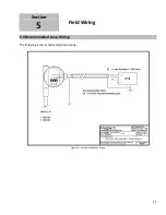
Page 14: ...Section 5 Field Wiring 5 0 Recommended Loop Wiring The following is the recommended loop wiring Figure 13 Recommended Loop Wiring 11...

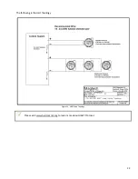
Page 15: ...The following is the Hart Topology Figure 14 HART Loop Topology Please visit www hartcomm2 org to learn more about HART Protocol 12...

Page 16: ...en exp conduit must be sealed within 18 inches of the termination point at the instrument Power must be supplied by an isolated supply Caution To reduce the risk of ignition of hazardous atmospheres d...

Page 17: ...Vdc 13V 20mA Repeatability 005 of full scale or 010 whichever is greater Non Linearity 01 of full scale or 030 whichever is greater Sensor Accuracy 01 of full scale or 030 whichever is greater Damping...

Page 18: ...change Yes to No and No to Yes This is the enter button used to execute functions and enter exit into or out of submenus The pushbuttons are timed not pressurized It does not matter how hard firm you...

Page 19: ...ace when option is provided in selected engineering units LTM 350 only 3 Temperature when option is provided in selected engineering units LTM 350 only 4 The analog current corresponding to level in m...

Page 20: ...el Interface Sel Alrm FailHigh FailLow HoldOut ChgRnge Sel LRV Sel URV Yes No yes 0 00 in 24 00 in SelDamp 1 sec ROC Fltr 10 0in s TrmSnsr TrimZero TrimZero TrimSpan TrimSpan Span Yes No yes Busy 24 0...

Page 21: ...t Length Note THIS IS NOT THE MEASURING RANGE This parameter should only reflect the overall sensor length It can be adjusted by incrementing and decrementing the value and then pressing enter Level U...

Page 22: ...changed from 0 00in to 3 00in the 4 00mA point will shift 3 00 inches higher than the original point It is recommended to leave this at 0 00 most of the time unless a special circumstance arises Press...

Page 23: ...er There is no need to recalibrate the instrument simply use the Change Range menu and change the LRV and URV as desired If the need arises to use this menu then level simulation will be required at 0...

Page 24: ...nt meter should be used to monitor the 4 20mA when this function is selected Test Loop This function allows for direct control of the Transmitter s current output mA capability Simply enter into this...

Page 25: ...mporary spontaneous noise that may be present in field For example if the level in a tank cannot rise or fall faster than 30 0 in s then the setting for the RoC filter should be set to 15 0 in s or le...

Page 26: ...t Default Select Defaults Yes No yes Load Save Load Factory Sensor1 Sensor2 Sensor 3 Loaded Select Defaults Save Sensor1 Sensor2 Sensor3 Saved v Deadzone 1 50in v 1pt Cal SelLngth Sel LRV Sel URV Ener...

Page 27: ...sired Loading Factory Defaults Enter into the Defaults menu by changing the no to a yes Then the option to Load will appear Press enter and the Factory option will appear then press enter on more time...

Page 28: ...t the factory for guidance with this parameter 6 The DCOffset menu is the signal to noise ration Please contact the factory for guidance with this parameter 7 The HoldTime menu is the amount of time t...

Page 29: ...onfiguration menu that is utilized to achieve this task To access this menu press and hold the increment button then while holding the increment button press and hold the enter button for 3 seconds 5...

Page 30: ...can be loaded if the parameters have been drastically changed Pulse Width Filter PW Filtr The pulse width filter can be utilized for dual output level and interface applications if there are any erron...

Page 31: ...Range menu and adjust the LRV or URV as desired 8 1 Troubleshooting Magtech manufactures custom built products so each transmitter has been specifically designed to fit on a magnetic level gage or be...

Page 32: ...ts terminal without affecting the analog current output The most common supply voltage used is 24Vdc At times additional resistance in the loop is necessary either in the form of a second load resisto...

Page 33: ...or a HART enabled host system HART Menu Flowchart for LTM350 Transmitter Device Setup Process Variables Level PV Value Note 1 Interface Note 2 Loop Current Temper Note 3 LRV Range URV Loop Current Di...

Page 34: ...its Note 3 Damping Detailed Setup Device Profiles Factory Slot Load User 1 Slot Load Save User 2 Slot Load Save User 3 Slot Load Save Signal Setup Energy DC Offset Hold Time Digital Level Alarms Alarm...

Page 35: ...Long Tag Message Descriptor Revision s Universal rev Fld dev rev Final asmbly num Note 1 When Interf is PV Interf is displayed Software rev Note 2 Only applies when interface float is included Hardwa...

Reviews: