background image

2

INTRODUCTION

This manual provides information and procedures to safely operate and maintain the engine and generator. For your 
own safety and protection from physical injury, carefully read, understand, and observe the safety instructions 
described in this manual. 

The information contained in this manual was based on machines in production at the time 

of publication. Magnum Products LLC reserves the right to change any portion of this information without notice.

DO NOT MODIFY or use this equipment for any application other than which it was designed for.

Magnum Products LLC recommends that a trained and licensed professional perform all electrical wiring and testing 
functions. Any wiring should be in compliance with the United States National Electric Code (NEC), state and local 
codes and Occupational Safety and Health Association (OSHA) guidelines.

Keep a copy of this manual with the unit at all times. Additional copies are available from Magnum Products LLC, or 
can be found at 

www.m-p-llc.com

. An engine operator’s manual was also supplied with the unit at the time of 

shipment from the factory. The manual provides detailed operation and maintenance procedures for the engine. 
Additional copies of the engine operators manual are available from the engine manufacturer.

MAGNUM PRODUCTS LLC

215 Power Drive • Berlin, WI 54923

U.S.A.

Phone: 920-361-4442

FAX: 920-361-4416

Toll Free: 1-800-926-9768

www.m-p-llc.com

For technical or parts QUESTIONS, please contact Magnum Products’ Customer Support or 

Technical Support team at 920-361-4442 or toll free at 1-800-926-9768. Please have your serial 

number available.

To ORDER SERVICE PARTS, please contact the dealer from which you purchased the unit, or call 

Magnum Products to locate a dealer in your area.

Supplemental information may be available for your unit; when ordering parts ALWAYS check for a 
supplement that applies to your unit. A supplement may have been provided with your unit and can 

be found on the Magnum Products LLC website.

Engine Make:__________________________________________
Engine Serial Number:___________________________________
Engine Model Number: __________________________________
Generator Make: _______________________________________
Generator Model Number: ________________________________
Generator Serial Number: ________________________________
Unit Model Number:_____________________________________
Unit Serial Number: _____________________________________

WARNING

CALIFORNIA PROPOSITION 65 WARNING:


Diesel engine exhaust and some of its 

constituents are known to the state of California to cause cancer, birth defects and 

other reproductive harm.

Summary of Contents for MMG 150

Page 1: ...DIESEL GENERATOR MMG150 MMG170 MMG235 OPERATING MANUAL ...

Page 2: ...ngine operators manual are available from the engine manufacturer MAGNUM PRODUCTS LLC 215 Power Drive Berlin WI 54923 U S A Phone 920 361 4442 FAX 920 361 4416 Toll Free 1 800 926 9768 www m p llc com For technical or parts QUESTIONS please contact Magnum Products Customer Support or Technical Support team at 920 361 4442 or toll free at 1 800 926 9768 Please have your serial number available To O...

Page 3: ...TROLLER MDC HISTORY 28 ADJUSTING THE DISPLAY BACK LIGHTING 28 RESETTING OF THE TIME TO SERVICE REMINDER 29 TROUBLESHOOTING AUTOMATIC SHUT DOWN CONDITIONS 29 GENERATOR OUTPUT CONNECTION LUGS 31 GENERATOR CAM LOCK CONNECTIONS OPTIONAL 32 VOLTAGE SELECTOR SWITCH MMG150 MMG170 ONLY 33 4 POSITION VOLTAGE SELECTOR SWITCH OPTIONAL 34 CHANGING OUTPUT VOLTAGE MMG235 ONLY 35 EMERGENCY STOP SWITCH 36 MAIN CI...

Page 4: ...ications DO NOT modify or use this equipment for any application other than which it was designed for Equipment operated improperly or by untrained personnel can be dangerous Read the operating instructions and familiarize yourself with the location and proper use of all instruments andcontrols Inexperiencedoperatorsshouldreceiveinstructionfromsomeone familiar withtheequipment before being allowed...

Page 5: ...can cause eye damage burn flesh or eat holes in clothing Protective eye wear and clothing are necessary when working on or around the battery Always disconnect the NEGATIVE battery cable from the corresponding terminal before performing any service on the engine or other components ELECTRICAL SAFETY The unit is powered by a generator driven by a diesel engine While the engine is running potentiall...

Page 6: ...n the trailer and tow vehicle will cause more weight to be carried by one axle which could cause premature wear on the tires and axles and cause potentially unsafe operating conditions The trailer is equipped with hydraulic surge brakes or electric surge brakes Check the operation of the brakes by braking the vehicle at a slow speed before entering traffic Both the trailer and the vehicle should b...

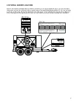
Page 7: ... PRESS DE GONF A FROID GAWR PNBE TIRE PNEU RIM JANTE KPA PSI LPC SGL DUAL THIS VEHICLE CONFORMS TO ALL APPLICABLE STANDARDS PRESCRIBED UNDER THE CANADIAN MOTOR VEHICLE SAFETY REGULATIONS IN EFFECT ON THE DATE OF MANUFACTURE CE VEHICULE EST CONFORME A TOUTES LES NORMES QUI LUI SONT APPLICABLES EN VERTU DU REGLEMENT SUR LA SECURITE DES VEHICULES AUTOMOBILES DU CANADA EN VIGUEUR A LA DATE SA FABRICAT...

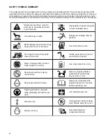
Page 8: ...the supplied operator s manual before operating unit Remove negative battery cable before performing any service on unit Stop engine before making connections Use clean diesel fuel only Unit electrical ground Hearing protection required while operating unit with doors open Anchor tie down point Lift here only Asphyxiation hazard Operate in well ventilated area Dangerous voltage may be present Neve...

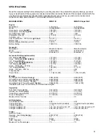
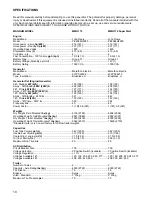
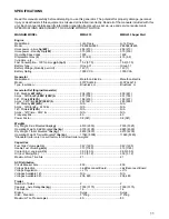
Page 9: ...3Ø Standby 480V 208V A 191 441 197 455 3Ø Prime kW kVA 116 145 119 149 Amps 3Ø Prime 480V 208V A 174 402 179 414 1Ø Standby kW kVA 114 114 128 128 Amps 1Ø Standby 240V A 475 533 1Ø Prime kW kVA 106 106 117 117 Amps 1Ø Prime 240V A 442 488 Frequency Hz 60 60 Power Factor 1 1Ø 0 8 3Ø 1 1Ø 0 8 3Ø Weights Dry Weight Skid Mounted lbs kg 5944 2696 6409 2907 Operating Weight Skid Mounted lbs kg 8500 3856...

Page 10: ... 3Ø Standby 480V 208V A 226 522 238 550 3Ø Prime kW kVA 137 171 144 180 Amps 3Ø Prime 480V 208V A 206 475 217 500 1Ø Standby kW kVA 125 125 154 154 Amps 1Ø Standby 240V A 521 642 1Ø Prime kW kVA 120 120 142 142 Amps 1Ø Prime 240V A 500 592 Frequency Hz 60 60 Power Factor 1 1Ø 0 8 3Ø 1 1Ø 0 8 3Ø Weights Dry Weight Skid Mounted lbs kg 6139 2785 6604 2996 Operating Weight Skid Mounted lbs kg 8567 388...

Page 11: ...enerator 3Ø Standby kW kVA 204 255 209 261 Amps 3Ø Standby 480V 208V A 307 708 251 724 3Ø Prime kW kVA 186 233 190 237 Amps 3Ø Prime 480V 208V A 280 647 285 658 1Ø Standby kW kVA N A N A Amps 1Ø Standby 240V A N A N A 1Ø Prime kW kVA N A N A Amps 1Ø Prime 240V A N A N A Frequency Hz 60 60 Power Factor 0 8 3Ø 0 8 3Ø Weights Dry Weight Skid Mounted lbs kg 6510 2953 7330 3325 Operating Weight Skid Mo...

Page 12: ...sused or installed incorrectly Read all of the manuals included with this unit Each manual details specific information regarding items such as set up use and service requirements SPECIFICATIONS ARE SUBJECT TO CHANGE WITHOUT NOTICE Dimensions L x W x H Skid Mounted in m 132 x 50 x 77 3 35 x 1 27 x 1 96 Trailer Mounted in m 210 x 86 x 93 5 33 x 2 18 x 2 36 50 132 77 86 210 93 ...

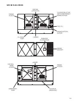
Page 13: ...13 SERVICE LOCATIONS ...

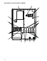
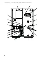
Page 14: ...14 MAIN CONTROL PANEL FEATURES STANDARD 1 2 3 4 7 8 9 10 11 12 13 15 14 5 6 ...

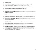
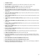
Page 15: ...INE BLOCK HEATER OPTIONAL Allows for 120VAC input to power the engine block heater 10 120V GFCI DUPLEX CONVENIENCE OUTLETS Outlets for additional equipment that may require Ground Fault Interrupt GFCI protection 11 REMOTE START TERMINAL BLOCK Used to connect the generator to a dry contact closure switch for remote starting of the generator 12 OUTPUT GROUND CONNECTION Ground lug for attaching the g...

Page 16: ...18 6 7 ENGINE ENGINE START START ENGINE ENGINE STOP STOP MANUAL AUTO ALARM CANCEL FAULT RESET ALARM FAULT READY MANUAL READY AUTO WARNING RUNNING SUPPLYING LOAD OPERATION PAGE SELECT ENTER DIAGNOSTICS STATUS CONTROL CONTROL ON ON CONTROL CONTROL OFF OFF MAN AUT Ready PF 0 00 RPM 0 0 kW 0 4 15 ...

Page 17: ...nput to power the engine block heater 10 120 240V TWIST LOCK CONVENIENCE OUTLETS 3 These outlets are used for connecting additional loads or equipment to the generator 11 REMOTE START TERMINAL BLOCK Used to connect the generator to a dry contact closure switch for remote starting of the generator 12 120V GFCI DUPLEX CONVENIENCE OUTLETS 2 Outlets for additional equipment that may require Ground Fau...

Page 18: ... the OPERATION keypad the LCD window the DIAGNOSTICS keypad and the STATUS Light Emitting Diodes LED s DIGITAL CONTROLLER FEATURES AND FUNCTIONS 1 The CONTROL ON OFF Toggle Switch and Fine Voltage Adjustment Screw CONTROL ON OFF Toggle Switch This toggle switch powers up the control panel and the controller Fine Voltage Adjustment Screw This screw may be adjusted to set the generator output voltag...

Page 19: ...that has not been reset Ready Manual Indicates the controller is ready to start and in the manual mode Ready Auto Indicates the unit is in the AUTO mode ready for the remote start signal Running Indicates the unit is running Supplying Load Indicates a load is being applied to the generator GENERATOR MONITORING Generator information is shown on the Liquid Crystal Display LCD window in a toggling ma...

Page 20: ...assword screen or History screen In each of these page selections the operator may press the S or T buttons on the DIAGNOSTICS keypad to display additional information as follows Running screen The operator may press the S or T buttons on the DIAGNOSTICS keypad to display the Alarm List screen ECU Alarm List screen Run Hours screen ECU Values screen Engine display screen and Generator display scre...

Page 21: ...witch on the control panel This screw turns a rheostat that will provide an increase or a decrease in the generator output voltage as displayed on the Power Display Screen on the control panel If the voltage is increased or decreased too fast or too slow the unit will automatically shut down This adjustment needs to be made within the 45 second delay and countdown to 0 Zero period To adjust the ou...

Page 22: ...h locked Is the generator sitting level Thoroughly check for any water inside the unit on or near the generator Dry the unit before starting Check oil coolant and fuel levels and engine battery connections Check engine fan belt tension and condition Check engine fan belt guard Check engine exhaust system for loose or rusted components Check radiator and surrounding shroud for debris Are any of the...

Page 23: ...r the engine to run smoothly and reach its governed operating speed The 45 second SENSING time delay will start to count down 7 The LCD window will then toggle from the Running screen to the Generator Display Screen and then to the Engine Display Screen 8 If the engine does not start after the first cranking attempt the engine will pause for 15 seconds to allow the starter to cool The LCD window w...

Page 24: ...ual Starting of the Generator sections beginning on page 22 Also follow all safety warnings and information on isolating the generator with a transfer switch if the unit is to be used as a standby power supply see page 38 Then continue with the steps described below 1 Perform a manual start of the generator at least once to verify that the engine is operating correctly 2 If a check of the remote s...

Page 25: ...ool Engine aftercooling Cooling Pump output is closed 2 Cooling The unit is cooling before stop 3 Cranking Engine is cranking 4 EmergMan Emergency Manual gen set operation 5 Init Autotest during controller power on 6 Loaded The unit is running at nominal speed and GCB OPEN CLOSE is closed 7 Not Ready The unit is not ready to start 8 Pause Pause between start attempts 9 Prestart Prestart sequence i...

Page 26: ... is smaller than Sd Oil press setpoint 16 Oil Press Wrn Warning WRN YES Oil pressure is smaller than Wrn Oil press setpoint 17 Overload SD YES The load is greater than the value given by Overload setpoint 18 Overspeed SD YES The protection comes active if the speed is greater than Overspeed setpoint 19 ParamFail NONE NO Wrong checksum of parameters Happens typically after downloading new firmware ...

Page 27: ...ondition must be resolved and the code cleared from the display Diagnostic messages are read and displayed in the ECU Alarm List The Suspect Parameter Number SPN Failure Mode Identifier FMI and Occurrence Counter OC are shown together with a description if possible One SPN FMI describes one failure If FMI is equal to zero or one WRN is displayed in the ECU Alarm list For any other FMI value FLS is...

Page 28: ... IOM IGS PTM Analog input 2 value when configured IG IOM IGS PTM 3 AIM3 IG IOM IGS PTM Analog input 3 value when configured IG IOM IGS PTM 4 AIM4 IG IOM IGS PTM Analog input 4 value when configured IG IOM IGS PTM 5 BIM IG IOM IGS PTM Binary inputs when configured IG IOM IGS PTM 6 BIN Binary inputs IL NT 7 BOM IG IOM IGS PTM Binary outputs when configured IG IOM IGS PTM 8 BOUT Binary inputs IL NT 9...

Page 29: ...ine controller will shut the engine down when there is five percent of fuel remaining in the tank This is done to keep the fuel lines from running dry 3 If the fuel level is good and no leaks are found check the fuel level sender and the connecting wiring fordamage Tocheckforcontinuitybetweenthesenderandtheenginecontroller removetheappropriate bolts from the control panel to access the inside of t...

Page 30: ...om the control panel to access the inside of the control box Consult the appropriate DC wiring diagram in the parts manual for the proper path between the engine controller and the temperature sender 8 If the sender and wiring are good and no other problems are found remove the load on the generator and restart the engine Observe the coolant temperature and shut the engine down immediately if it s...

Page 31: ...rator connection lugs DANGER IMPROPER OR INCORRECT CONNECTIONS TO A BUILDINGS ELECTRICAL SYSTEM CAN CAUSE POTENTIALLY LETHAL VOLTAGES TO BACKFEED ONTO UTILITY LINES THIS MAY RESULT IN INJURY OR ELECTROCUTION TO UTILITY WORKERS NEARBY MAKE SURE THE GENERATOR IS SUPPLING POWER TO AN ISOLATED OBJECT OR BUILDING THAT IS NOT CONNECTED TO ANY UTILITY LINES Connections to the lugs should be made by runni...

Page 32: ...ES THIS MAY RESULT IN INJURY OR ELECTROCUTION TO UTILITY WORKERS NEARBY MAKE SURE THE GENERATOR IS SUPPLYING POWER TO AN ISOLATED OBJECT OR BUILDING THAT IS NOT CONNECTED TO ANY UTILITY LINES Connections should be made by plugging power cables equipped with series 16 taper nose 400A 600V cam lock plugs into the cam lock receptacles Secure the connection by rotating the plug a 1 4 turn to the right...

Page 33: ...le up and insert a padlock through the handle By locking the handle in place you will prevent unauthorized personnel from changing the switch settings Note When the voltage selector switch is in position for 480 277V 3Ø voltage at the two GFCI duplex convenience outlets is 139 Volts and the voltage at the three twist lock outlets is 240 139 Volts When the voltage selector switch is in position for...

Page 34: ...rt a padlock through the handle By locking the handle in place you will prevent unauthorized personnel from changing the switch settings Note The following applies to units without a convenience outlet buck transformer When the voltage selector switch is in position for 277 480V 3Ø voltage at the two GFCI duplex convenience outlets is 139 Volts and the voltage at the three twist lock outlets is 13...

Page 35: ...g link board must be attached in the lower position as shown in the illustration For 208 120 3Ø voltage the shorting link board must be in the upper position as shown in the illustration If the board needs to be changed from one setting to the other remove all of the 1 2 nuts that hold the shorting link board down and move it to the new position Replace all of the hardware and tighten it to 25 ft ...

Page 36: ...osition Use the breaker handle extension supplied with this unit to apply additional leverage to the switch The main circuit breaker will be tripped disconnecting power to the connection lugs if any of the following items occur while the unit is running 1 Overload of the generator circuits to the connection lugs 2 The door covering the customer connection lugs is opened 3 If the emergency stop swi...

Page 37: ...e twist lock outlets and the two GFCI outlets is 208 120 volts DERATING FOR ALTITUDE All generator sets are subject to derating for altitude and temperature this will reduce the available power for operating of tools and accessories connected to the auxiliary outlets Typical reductions in performance are 2 4 for every 1000 ft 305 meters of elevation and 1 per 10º F 3 5º C increase in ambient air t...

Page 38: ...RE THE GENERATOR IS ISOLATED BY A TRANSFER SWITCH FROM ANY LOCAL UTILITY LINES THIS ALSO APPLIES IF THE GENERATOR IS BEING USED AS A BACK UP TO SOME OTHER TYPE OF POWER SUPPLY Installation of a transfer switch or other type of remote starting device is the responsibility of the generator user Installation of such devices must be performed by following all directions supplied by the manufacturer of...

Page 39: ... inadvertently trying to start the unit If the unit is connected to a remote start or transfer switch make sure the remote switch is also off and tagged Never wash the unit with a high pressure hose or with any kind of power washer Never wash the engine block or fuel tank with a power washer or steam cleaner Water may enter the cabinet and collect in the generator windings or other electrical part...

Page 40: ...ade of oil including special operating conditions such as a change in season or climate Check the coolant level daily The coolant is checked by visually inspecting the level in the coolant overflow jug located near the radiator The normal operating level is anywhere between the FULL and ADD markings on the overflow jug with the optimum level noted as NORMAL RANGE Coolant may be added directly to t...

Page 41: ...latched 4 Check for proper inflation of the trailer tires Maximum tire pressures can be found on pages 9 11 5 Check the wheel lugs Tighten or replace any that are loose or missing If a tire has been removed for axle service or replaced tighten the lugs in the order shown to the following specifications A Start all lug nuts by hand B First pass tighten to 20 25 Ft Lbs 27 33 Nm C Second pass tighten...

Page 42: ...n allows the fuel tank to be refilled from an external bulk fuel source When the fuel transfer switch is on anytime the fuel level drops below 15 the fuel transfer pump will begin pumping fuel from an external bulk fuel source into the fuel tank on the unit The fuel transfer pump will shut off when the fuel level of the internal tank reaches 90 The pump will also be monitored to ensure a certain p...

Page 43: ...ARKER LAMP AMBER MARKER LAMP AMBER MARKER LAMP AMBER MARKER LAMP RED MARKER LAMP IDENTIFICATION LIGHT BAR PLATE LAMP RED MARKER LAMP STOP TURN SIGNAL LAMP LEFT STOP TURN SIGNAL LAMP RIGHT FENDER FENDER TRAILER WIRING DIAGRAM ...

Page 44: ...44 BLK BLU GREEN YELLOW BROWN WHITE BREAK AWAY SW BATT TO BRAKES RIGHT TURN STOP LEFT TURN STOP TAIL MARKER GROUND ELECTRIC BRAKE WIRING HARNESS ...

Page 45: ...5 18 22 26 19 20 23 24 27 28 T9 RCPT 240V 50A 50A RCPT 240V BLK BLK BLK T6 T8 T10 T11 T7 T1 T12 T2 T3 GENERATOR F F 120V 20A BRKER 120V RECPT GFCI L3 L2 L1 L0 SE350 VOLTAGE REGULATOR 12VDC T9 GRN YEL BRKER 20A 120V GND BLK RED LUG DOOR NO 12 11 SAFETY SWITCH LT BLU LT BLU LT BLU LT BLU LT BLU BLK BLK PAIR BLK L0 NC NO COM H1 H3 X4 X2 H2 H4 X1 X3 BLK RED WHT WHT QTY 2 BRN BLK RELAY BUCK XFORMER 2 7...

Page 46: ...T6 T8 T10 T11 T7 T1 T12 T2 T3 GENERATOR F F 120V 20A BRKER 120V RECPT GFCI 6GA L2 SE350 VOLTAGE REGULATOR 6GA 6GA 12VDC T9 GRN YEL BRKER 20A 120V GND 3 JUMPER WIRES DASHED ON PHASE SWITCH 10GA BLK RED PLUG 21 PIN 6 AWG CIRCUIT 24 23 NO LUG DOOR NC 12 11 SAFETY SWITCH L3 L2 L1 N WHT YEL BRN ORN P P N N 34 33 29 30 36 35 32 31 37 38 39 40 2 7 8 1 4 6 5 3 BRN W BRN RED GRN WHT BR BLK ORN YEL BLK VOLT...

Page 47: ...0V RCPT 240V 50A 50A RCPT 240V BLK BLK BLK GENERATOR F F 120V 20A BRKER 120V RECPT GFCI 3 0 SE350 VOLTAGE REGULATOR 12VDC T9 GRN YEL 14GA BRKER 20A 120V GND L0 PAIR BLK 6GA LT BLU 10GA LT BLU 10GA LT BLU 10GA LT BLU 10GA BLK RED 6 AWG CIRCUIT BOARD RECONNECT T5 T10 T11 T12 T4 T6 T8 T7 L1 T9 L2 L3 T7 480V SHORT 208V SHORT T10 T11 T12 T1 T2 T3 T4 T5 T6 T8 T9 3 0 3 0 QTY 3 BLK 3 0 RECONNECT DOOR SAFE...

Page 48: ...BLK BLK BLK GENERATOR F F 120V 20A BRKER 120V RECPT GFCI 3 0 SE350 VOLTAGE REGULATOR 12VDC T9 GRN YEL 14GA BRKER 20A 120V GND L0 PAIR BLK 6GA LT BLU 10GA LT BLU 10GA LT BLU 10GA LT BLU 10GA BLK RED 6 AWG CIRCUIT T7 T10 T11 T12 T3 T2 T1 T4 T5 T6 T8 T9 3 0 3 0 24 23 NC NO NC NO COM H1 H3 X4 X2 H2 H4 X1 X3 BLK 10GA RED 10GA WHT 10GA WHT 14GA QTY 2 BRN 14 BLK 10GA RELAY BUCK XFORMER TO BREAKER SHUNT S...

Page 49: ...ON WATER IN FUEL IN OIL IN PIN 3 PIN PLUG ANALOG INPUTS PLUG LOCATION WHT AI1 OIL AI3 FUEL AI2 TEMP REMOTE START BI2 BI3 BI4 BI5 BI6 OPEN OPEN LOW COOLANT OPTION C2 12VDC BO2 SRT FUE BO3 BO4 BO5 BO6 OPEN OPEN OPEN OPEN GND ON BOARD BO2 FUEL BO1 START COM L H ECU COM PIN LOCATION PLUG LOCATION ECU H 3 PIN PLUG ECU L SHIELD BLK GRY DEUTSCH 21 PIN F CAN SHLD CAN L 21 PIN U DEUTSCH DEUTSCH 21 PIN V CA...

Page 50: ... AI2 TEMP REMOTE START BI2 BI3 BI4 BI5 BI6 OPEN OPEN LOW COOLANT OPTION C2 12VDC BO2 SRT FUE BO3 BO4 BO5 BO6 RECONNECT DOOR OPEN OPEN OPEN NOT REQUIRED WITH JOHN DEERE ECU ENGINE GND ON BOARD BO2 FUEL BO1 START COM L H ECU COM PIN LOCATION PLUG LOCATION ECU H 3 PIN PLUG ECU L SHIELD BLK GRY DEUTSCH 21 PIN F CAN SHLD CAN L 21 PIN U DEUTSCH DEUTSCH 21 PIN V CAN H BLK Shield not connected Cut back an...

Page 51: ..._______________ __________________________________________________________________________________________ __________________________________________________________________________________________ __________________________________________________________________________________________ __________________________________________________________________________________________ ____________________...

Page 52: ...REV F PART NO 26277 01 11 10 ...

Reviews: