background image

M C C - 3 5 A S             

19 

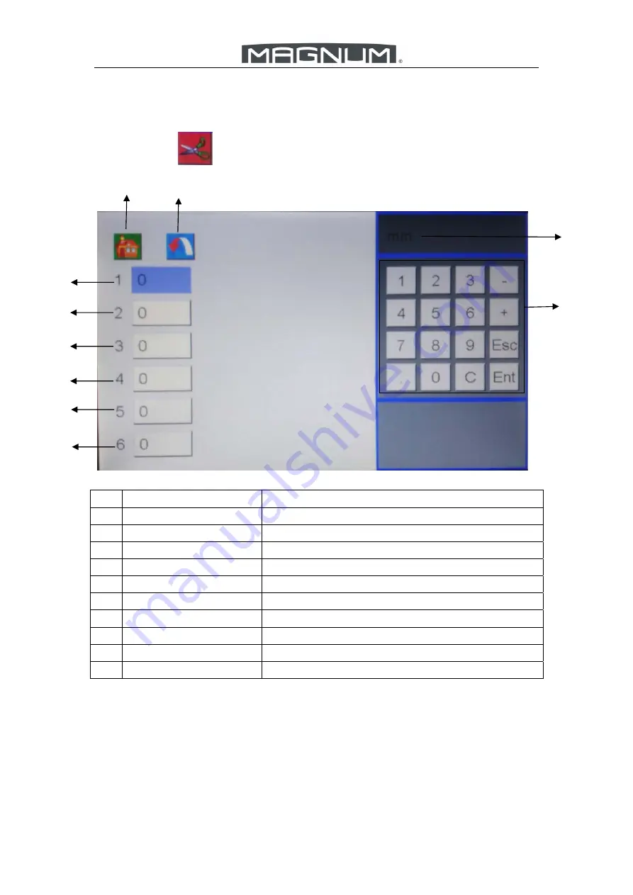
5.5.2.2


Slit


Setting


Press the icon

, entering slit data setting screen. 

No.  Description 

Remark 

Home 

Back to Main Screen. 

Return 

Return to the last page 

Unit 

Data unit mm or inch. 

Keyboard 

Input all data according local request. 

Slitter #1 Data 

Set slitter #1 data 

Slitter #2 Data 

Set slitter #2 data 

Slitter #3 Data 

Set slitter #3 data 

Slitter #4 Data 

Set slitter #4 data 

Slitter #5 Data 

Set slitter #5 data 

10  Slitter #6 Data 

Set slitter #6 data 

3

10 

4

Summary of Contents for MCC-35ASP

Page 1: ...nual Magnum MCC 35ASP The Magnum has been designed to be user friendly however we strongly recommend you take a few minutes to read through this manual to ensure correct operation Keep this manual saf...

Page 2: ...5 3 Main Screen 14 5 4 Main Running Screen 15 5 5 Manual Programming Screen 16 5 5 1 Main Icon Introduction 16 5 5 2 Manual Input 17 5 5 2 1 Paper Size Setting 17 5 5 2 2 Slit Setting 19 5 5 2 3 Cut...

Page 3: ...2 2 What is barcode 37 6 2 2 1 Code 39 37 6 2 2 2 Definition of a complete Magnum barcode 37 6 2 3 How to create barcodes 38 6 2 4 Where should the barcode print on the layout 41 6 2 5 How the barcod...

Page 4: ...am Weight 150g 350g 0 15 0 35mm Output Size Max W L 330mm 650mm Min W l 50mm 48mm Cross Cutter First Cut 3 2 15mm Last Cut 5 15mm Gutter Cut 3 15mm Min Card Size for Cutter 48mm Max Qty for Cutter per...

Page 5: ...ing 100mm Double Feed Detect Ultrasonic Detecting Skew Adjustment Manually Adjustment Image Compensation X Y Direction Compensation User Template Storage 64 Note The machine is keep upgrading specific...

Page 6: ...ctrical components Power supply AC input Voltage Frequency is AC 110 240V 50 60Hz If the voltage or frequency are not in the range the machine may not be used normally or even may cause unrecoverable...

Page 7: ...make sure all safety covers are in place The top covers have an interlock switch which will disable the unit if removed Do open or close the cover slowly Do contact the local maintenance center befor...

Page 8: ...e running Don t put heavy matter on machine or shock it Don t put the side guide under the feeding system 2 3 Cautions Be careful of any metal or flammable thing in internal machine or it may cause fi...

Page 9: ...4 Outfeed Tray Collecting finished Bigger Cards or Sheets 5 Stand Place Waste Box and Store Room for parts or sheets 6 Crease Side Cover Exchange the crease die or perforating die 7 Lock device Protec...

Page 10: ...oating too much 5 Air Blast Knob Adjust the air blast 6 Paper Separator Knob Adjust the height of separator to change the gap between separator and vacuum belt according to different paper thickness 7...

Page 11: ...e SC cover is closed well 3 1 Slitter 4 2 Slitter 5 3 Slitter 6 Cutter Aligned Sensor Detect the paper before cutter 7 Lag Wheel A Adjust pressure of two rollers before cutter 8 Lag Wheel B Adjust pre...

Page 12: ...Perf Option 3 Outfeed Lower Roller Shaft Fix the anvils of all option linear tools 4 Outfeed Lower Roller Work with outfeed lag wheel to outfeed cards 5 Outfeed lag wheel Work with outfeed lower rolle...

Page 13: ...ures 1 Remove the back cover of touch screen as picture and 2 Connect the cable to the screen drive board as picture and Mind avoiding damage the screen cable 3 Fix the screen onto machine as picture...

Page 14: ...flectors and side guide as following picture 4 5 Power Socket and Switch AC input Voltage Frequency is AC110 240V 50 60Hz Cautions Don t operate machine with wet hand Side Guide Post Deflectors Movabl...

Page 15: ...rent total sheet qty the machine has run Number of cut The current total qty the cross cutter has worked Number of crease The current total qty the creaser has worked SN The serial number of the machi...

Page 16: ...libration Use a tiny pen to click the red dot step by step then it will back to welcome screen again after the calibration is finished This function is for the issue that the clicked icon doesn t matc...

Page 17: ...torage Recall the user template 4 Preset Template Storage Recall the factory template 5 Communicating with PC Reserved function 6 Settings Enter into system settings of machine 7 Tray Down Let loading...

Page 18: ...Sheets Qty per Batch Set the sheets qty in one batch 5 Batch Qty Set the batch qty 6 Start Machine starts to work 7 Test Machine runs current template one sheet 8 Check Locate the linear tool positio...

Page 19: ...c crease depth black mark position 3 Slit Data Set the data of Slitters 4 Cut data Set the data of Cross Cutter 5 Crease Data Set the data of Creaser 6 Image Compensation For dealing with the images s...

Page 20: ...erf 4 6 Image Compensation For dealing with the images shift or shrink stretch caused by printing 7 Start Enter Running Screen 8 Back Page Back to last page 9 Save As Save the temper template with a n...

Page 21: ...ing to paper thickness 4 Unit Data unit mm or inch 5 Keyboard Set all data according local request 6 Standard Paper Size Set standard paper length and width 7 Register Mark Setting Set position data o...

Page 22: ...rn Return to the last page 3 Unit Data unit mm or inch 4 Keyboard Input all data according local request 5 Slitter 1 Data Set slitter 1 data 6 Slitter 2 Data Set slitter 2 data 7 Slitter 3 Data Set sl...

Page 23: ...setting screen No Description Remark 1 Home Back to Main Screen 2 Return Return to the last page 3 Keyboard Input all data according local request 4 Next Turn to Next Page 17 32 cut position data 5 C...

Page 24: ...setting screen No Description Remark 1 Home Back to Main Screen 2 Return Return to the last page 4 Keyboard Input all data according local request 4 Next Turn to Next Page 17 32 crease position data 5...

Page 25: ...22 5 5 2 5 Partial Perforating Setting 1 Press the Next icon of manual programming screen entering Partial Perforating setting screen 2 Press the icon entering strike perforator 1 data setting screen...

Page 26: ...perforator 2 3 4 partial perforating position data is the same with strike perforator 1 Press icon to set Each pair partial perforating position data is made up of two data The upper data means start...

Page 27: ...ng Screen 5 6 1 Introduction of Sheet Data Example Card size 90mmx200mm Paper size SAR3 thickness 300gsm Crease in the middle partial perforating from middle to tail Lead trim 10mm side trim 15mm Gutt...

Page 28: ...e in the middle partial perforating from middle to tail Lead trim 10mm side trim 15mm Gutter cut 30mm Gutter slit 10mm 5 6 2 1 Set Paper Size Press SRA3 shortcut key to input length and width or input...

Page 29: ...26 5 6 2 2 Set Card Size Input the card size data and press Next icon to set trim and gutter 5 6 2 3 Set Trim and Gutter Input the trim and gutter data press Next icon to set crease perforating data...

Page 30: ...or input the crease data by keyboard directly Press Next icon to set partial perforating data for each finished piece 5 6 2 5 Set Partial Perforating Data for Each Finished Piece Input the partial per...

Page 31: ...mplate Check if the template is same with the sample If not Press Back icon to check the setting process again If yes press OK icon to run the template Press icon to data screen and then press icon to...

Page 32: ...e 5 7 1 Save a Template Press icon to save template to the user template storage 5 7 2 Recall a Template Press icon to recall a user template from the user template storage Press icon to recall a fact...

Page 33: ...M C C 3 5 A S 30 5 8 System Setting Press icon entering system setting screen User Mode some common function for user As for Service Mode please refer to the Technician Manual for details...

Page 34: ...1 Reg slit mark X should be between 100 117 mm from the right edge of paper Reg cut mark Y should be between 3 15 mm from leading edge 2 The black mark itself should be more than 3 5 L 5mm W 3mm 3 All...

Page 35: ...M C C 3 5 A S 32 2 Select register mark function...

Page 36: ...in all the number keyboard of the machine is a dual function 1 Click icon once the value will increase by 0 1mm or 0 001inch Such as Origin value is 5 click once it turns to be 5 1 Click icon once th...

Page 37: ...M C C 3 5 A S 34 2 Press icon for 3 seconds the icon turns green Such as Origin value is 5 1 input value 50 and the click ENT icon it turns to be 55 1...

Page 38: ...the sliding easy we install the screw on the bar For Crease tools 1 0mm version is standard Optional version is 0 6mm 1 2mm 1 4mm For Perforate tools there are8 TPI 12 TPI and 24TPI version all are fo...

Page 39: ...vention has to be done with the process when the job should be changed Barcode reader is a solution of this kind of intelligence upgrading If a machine is equipped with barcode reader and correspondin...

Page 40: ...ode in near future which is based on code39 6 2 2 1 Code 39 Code 39 is one of the protocols that define symbols as barcodes The definitions are as following Each code consist of 9 bars 5 in black 4 in...

Page 41: ...a zer0 0 before that say 065 if it is less than 10 insert 2 zeros 00 before that say 002 Symbol 5 6 Qty for each job This 2 number is the sheet qty for this job Mind that the code should be double di...

Page 42: ...s enter CONTROL PANEL copy the code39 ttf to the folder Font The font will be installed automatically Step 3 Then when you are using software that should be input text like Word Excel Photoshop Adobe...

Page 43: ...is 0 5mm wide The width will be exact if you choose 21 font size Step 4 At last when you are making the layout with any software remember to edit barcode on the specified area Fox example if this layo...

Page 44: ...and the end of the string tells the system that the numbers between them is valid or all value will be ignored First 3 values will points to the program number that will be recalled For example If the...

Page 45: ...ob Also take the above example 1 5 4 2 0 Machine will count the job after a sheet is completely passed Before the counter reach 20 no barcode will be read But after 20 is reached the barcode reader wi...

Page 46: ...M C C 3 5 A S 43 Chapter 7 Trouble Shooting 7 1 Show warning C 4 C 6 C 7 C 8 C 4 Crease unit cover open C 6 Crease unit side cover open...

Page 47: ...M C C 3 5 A S 44 C 7 SC unit safety cover open C 8 SC Unit waste bin door open Please check corresponding cover is closed well...

Page 48: ...C 12 Double feed 1 Check if it is really double feed If yes adjust the gap between separator and vacuum belt by paper separator knob Adjust the air blast knob to make sure the paper is floating 2 If...

Page 49: ...S 46 7 3 Show warning C 9 C 9 Paper jam at infeed table 1 Clean the paper dust by air gun on the sensor 2 Adjust the gap between separator and vacuum belt if they are too close 3 The side guide keeps...

Page 50: ...M C C 3 5 A S 47 7 4 Show warning C 10 1 Clean the jam paper between the out feed roller 2 Clean the paper dust by air gun on the sensor...

Page 51: ...M C C 3 5 A S 48 7 5 Don t show warning C 2 when tray empty Clean the paper dust by air gun on the sensor...

Page 52: ...M C C 3 5 A S 49 7 6 Show warning C 5 Please check if the crease perf die is in place 7 7 Show warning C 11 C 11 Paper jam near cutter...

Page 53: ...7 8 Show Error E 3 Load too much paper at one time the pile height is over 100mm remove some paper from loading table 7 9 Show Error E 2 E 2 Elevator Error 1 The loading table is at the top position s...

Page 54: ...eleasing Button the other hand operates the touch screen pressing Tray Down icon the tray will go down to lower position 2 The loading table is at the lower position showing error E 2 One hand keeps p...

Page 55: ...hand keeps pressing the Releasing Button the other hand operates the touch screen pressing Start icon to run machine and loading table will go up One hand keeps pressing the releasing button The other...

Page 56: ...cut data decreases by 0 1 for each click All slit data increases by 0 1 for each click All cut data increases by 0 1 for each click All slit data decreases by 0 1 for each click All cut data decrease...

Page 57: ...the sheet 2 Click the icon to increase the cut data by 0 1 each time and run one sheet to check until the color edge is nearly the same 3 If the color edge is nearly the same but the color edge is big...

Page 58: ...with wet cloth and infeed outfeed sensors with air gun while machine used for long time Meanwhile the working environment should be clean and dry as well as no light shining directly Technician maint...

Page 59: ...and tear this does not cover film jams misfeeds or other operator related errors which would be chargeable Your MCC 35AS is covered against manufacturing defects it does not cover against any damages...

Reviews: