


2
46-620 B73 & Series 75 Liquid Level Switches
1.4
Mounting
Caution:
This instrument is intended for use in Installation
Category II, Pollution Degree 2.
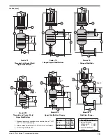
Adjust piping as required to bring control to a vertical
position. Magnetrol controls must be mounted within
3° of vertical in all directions. A three degree slant is
noticeable by eye, but installation should be checked with
a spirit level on top and/or sides of float chamber.
Controls should be mounted as close to the vessel as possi-
ble. This will result in a more responsive and accurate level
change in the control. Liquid in a long line may be cooler
and more dense than liquid in the vessel causing lower
level indication in the control than actual level in the vessel.
Caution:
Never insulate the switch housing of the level control.
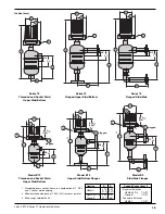
Installation and maintenance of tandem float models are
accomplished in much the same manner as described for
standard models. Additional consideration must be given
to the piping arrangement to allow for alignment of the
two switch actuating level marks on the float chamber
with the desired levels in the vessel.
1.5
Wiring
Caution:
Level controls are shipped from the factory with the
enclosing tube tightened and the middle set screw, on the
housing base, locked to the enclosing tube. Failure to
loosen the set screw prior to repositioning the conduit
connection may cause the enclosing tube to loosen,
resulting in the possible leakage of the process liquid
or vapor.
B73 and Series 75 controls are shipped with the conduit
entry of the switch housing placed 180° opposite to the
tank configurations to simplify installation in most cases.
If this configuration is appropriate to the installation, pro-
ceed to Step 4 to begin wiring the unit. If another configu-
ration is desired, the switch housing can be easily rotated
by first following Steps 1, 2, and 3.
NOTE: A switch or circuit breaker shall be installed in close proximity
to equipment and within easy reach of operator. It shall be
marked as the disconnecting equipment.
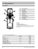
1. Loosen set screw(s) at base of switch housing. Refer to
Figure 2.
2. Switch housing may be rotated 360° to allow correct
positioning of conduit outlet.
Set Screw
Screw
Screw
Figure 2
Switch Housing


