


1
46-620 B73 & Series 75 Liquid Level Switche
s
1.0
Installation
Caution:
If equipment is used in a manner not specified by manu-
facturer, protection provided by equipment may be
impaired.
1.1
Unpacking
Unpack the instrument carefully. Inspect all units for
damage. Report any concealed damage to carrier within
24 hours. Check the contents of the packing slip and
purchase order. Check and record the serial number for
future reference when ordering parts.
1.2
Critical Alarm Function
It is recommended that for critical alarm functions, an
additional level switch be installed as a high–high or
low–low level alarm for maximum protection.
1.3
Piping
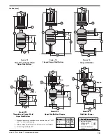
Figure 3 shows a typical piping installation of a Magnetrol
B73 and Series 75 control to a pressure vessel. Level decals
on control identify the actuation levels for a unit with a
single switch at minimum specific gravity. See
Section 5.2,
Physical
on page 17 for the actuation levels.
Use pipe of sufficient strength to support the control. If
necessary, provide a stand or hanger to help support its
weight. All piping should be straight and free of low spots
or pockets so that lower liquid line will drain towards the
vessel and upper vapor line will drain toward the control.
Shut-off valves are recommended for installation between
the vessel and the control. If control is to be used with a
low temperature liquid (one which will boil in the float
chamber if outside heat is absorbed), the chamber and pip-
ing should be insulated. Such boiling in the chamber will
cause false level indications.
Caution:
Do not insulate switch mechanism housing.
On controls equipped with pneumatic switch assemblies,
consult bulletin on mechanism furnished for air (or gas)
piping instructions. See
Section 6.1.2, Switch and Housing
Reference
on page 19 for bulletin numbers for pneumatic
switches.
NOTE: D, E, and H75 models are designed for high level service only
and utilize a pressure equalizing self-purging float and stem.
Pressure in the chamber must be raised and lowered slowly to
avoid potential float collapse.
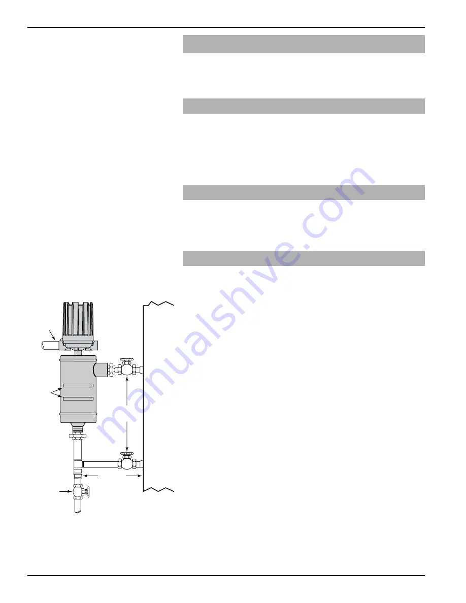
Shutoff
valve
Drain
valve
Conduit
outlet
Max. 12"
Pressure
vessel
Switch
actuating
level
reference
marks
Figure 1
Piping Configuration


