


7
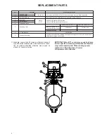
DIMENSIONAL SPECIFICATIONS in mm (inches)
OUTLINE DIMENSIONS IN mm (inches)
A
B
C
D
C
A
B
C
D
HL
LL
C
A
B
C
D
Dimensions
Specific gravity
0.60
0.80
1.00
1.20
HL
30 (1.22)
43 (1.69)
49 (1.93)
54 (2.13)
LL
53 (2.10)
60 (2.36)
65 (2.56)
68 (2.68)
ACTUATING LEVEL DIMENSIONS VS.
SPECIFIC GRAVITY – mm (inches)
Threaded & Socket weld
upper side/bottom
Flanged
upper side/bottom
Flanged
side/side
159 ± 2 (6.26 ± 0.08)
for material code 1 & 2
163 ± 2 (6.42 ± 0.08)
for material code 4
250 ± 2
(9.84 ± 0.08)
250 ± 2
(9.84 ± 0.08)
83 ± 2
(3.27 ± 0.08)
160 ± 2
(6.30 ± 0.08)
160 ± 2
(6.30 ± 0.08)
Housing
A
B
Entry C
max D
➃
IP 65 (NEMA 4x)
151 (5.93)
109 (4.29)
1" NPT, M20 x 1.5 or PG16 (2 entries - 1 plugged)
459 (18.07)
NEMA 7/9 (IP 65)
143 (5.63)
100 (3.94)
1" NPT - 1 entry
453 (17.83)
CENELEC/BASEEFA (IP 66)
143 (5.63)
110 (4.33)
3/4" NPT OR M20 x 1.5 - 2 entries
507 (19.80)
NEMA 3R (IP 53) Pneumatic K
118 (4.64)
130 (5.12)
1/4" NPT - 2 entries
423 (16.65)
NEMA 3R Pneumatic J
118 (4.64)
110 (4.33)
1/4" NPT - 1 entry
423 (16.65)
➃
Allow ± 3 (0.12) tollerances on dimensions and allows 203 (8.00) overhead clearance for cover removal


