


3
INSTALLATION
CRITICAL ALARM FUNCTION
It is recommended that for critical alarm functions, an addi-
tional level switch be installed as a high-high or low-low
level alarm for maximum protection.
PIPING
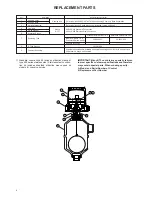
Figure 3 shows a typical piping installation of a Magnetrol
level switch to a pressure vessel. Reference mark on float
chamber should be aligned to correspond with liquid level
in vessel at which switch control is desired.
Use pipe of sufficient strength to support the control. If nec-
essary, provide a stand or hanger to help support its
weight. All piping should be straight and free of “low spots”
or “pockets” so that lower liquid line will drain towards the
vessel and upper vapor line will drain toward the control.
Shut-off valves are recommended for installation between
the vessel and the control. If control is to be used with a
lower temperature liquid (one which will “boil” in the float
chamber if outside heat is absorbed), the chamber and pip-
ing should be insulated. Such boiling in the chamber will
cause false level indications. DO NOT INSULATE SWITCH
MECHANISM HOUSING.
On controls equipped with pneumatic switch assemblies,
consult bulletin on mechanism furnished for air (or gas) pip-
ing instructions. Refer to chart on this page for bulletin num-
bers for pneumatic switches.
MOUNTING
Adjust piping as required to bring control to a vertical posi-
tion. Magnetrol controls must be mounted within three (3°)
degrees of vertical. A three degree slant is noticeable by
eye, but installation should be checked with a spirit level on
top and/or sides of float chamber.
Controls should be mounted as close to the vessel as pos-
sible. This will result in a more responsive and accurate
level change in the control. Liquid in a long line may be
cooler and more dense than liquid in the vessel causing
lower level indication in the control than actual level in the
vessel.
cable entry
Pressure
vessel
Switch
actuating
level
reference
marks
Drain
valve
Shutoff
valve
Max
305 mm
Figure 3
WIRING
Most mechanical control switch housings are designed to
allow 360° positioning of the cable entries by loosening the
set screw(s). See figure 4. On high temperature applica-
tions (above 120° C [250° F]), high temperature wire should
be used between control and first junction box located in a
cooler area.
1. To gain access to switch mechanism(s) remove switch
housing cover. (See CAUTION next page.)
2. Pull in supply wires (conductors), wrap them around
enclosing tube under the baffle plate and connect to
proper terminals. Be certain that excess wire does not
interfere with "tilt" of switch and that adequate clearance
exists for replacement of switch housing cover.
NOTE: See bulletin on switch mechanism furnished with
your control (as listed below) for proper connections.
3. Connect power supply to control and test switch action
by varying liquid level in tank or vessel.
CAUTION:
In hazardous area, do not power the unit until
the cable gland is sealed and the enclosure
cover is screwed down securely.
NOTE: If switch mechanism fails to function properly, check
vertical alignment of control housing and consult installation
instructions in switch mechanism bulletin.
4. Replace switch housing cover and place control into ser-
vice.
NOTE: If control has been furnished with an explosion proof
(cast) or moisture proof (gasketed) switch housing, check
the following:
– After wiring connections have been completed, housings
must be sealed via the correct cable gland to prevent
entrance of air.
– Check cover to base fit, to be certain gasketed joint is
tight. A positive seal is necessary to prevent infiltration of
moisture laden air or corrosive gases into switch housing.
Switch mechanism
Bulletin
Reference series
Mercury switches
42-783
A
Dry contact switches
42-683
B, C, D, U, W, X
Anti-vibration mercury switches
E
Anti-vibration dry contact switches
42-684
G, H, I
Bleed type pneumatic valve
42-685
J
Non-bleed type pneumatic valve
42-686
K


