Pedestrian Barrier High Door MPH 112
Electrical connection
54
5817,5005EN / Version 01
LS
1
LS
3B
LS
3A
LS
2
LS
4B
LS
6
LS
4A
LS
5
Mag00020a
ENTRY
EXIT
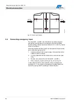
Fig. 22: Position light barriers
8.4
Connecting emergency input
The inputs IN1– and IN1+ are intended to be used as superior
emergency opening inputs, for example for fire alarm systems.
Factory setting of these inputs are defined at 0 V or 24 V by means
of two wire jumpers.
Several pedestrian barriers should be interrupted at the same time
by a central emergency switch:
1. Install a customer’s 24V power supply in the external control
cabinet to drive the relays.
2. In every pedestrian barrier install each a customer two-pole
relay.
3. Remove wire jumpers from terminals IN1– and IN1+.
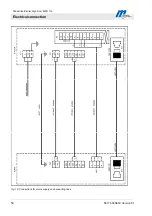
4. Wire emergency input according to Fig. 21 and Fig. 23.
In case that input IN1 is interrupted the motor end-stages are
powered off, i. e. the motors are powerless, the glass wings are
opened by springs and the passage is completely free.


