


SMART TRAC DM6420 Multi I/O Card
Engineer's Guide EM-3643-0050 Software Configuration
••
11
logic means that a high voltage condition reads as a Boolean
TRUE.
•
Select
Port 1 Direction
as input or output. For Port 1, the entire
byte must be configured as input or output.
•
Select a
Logic Type
for Port 1, either Positive or Negative. As
above, Negative means that a high voltage condition reads as a
Boolean FALSE. Positive logic means that a high voltage
condition reads as a Boolean TRUE.
10. When done making selections, click
CANCEL
to back out of the
selections without saving them or click
OK
to save your selections.
You are returned to the
DM6420 Configuration
screen.
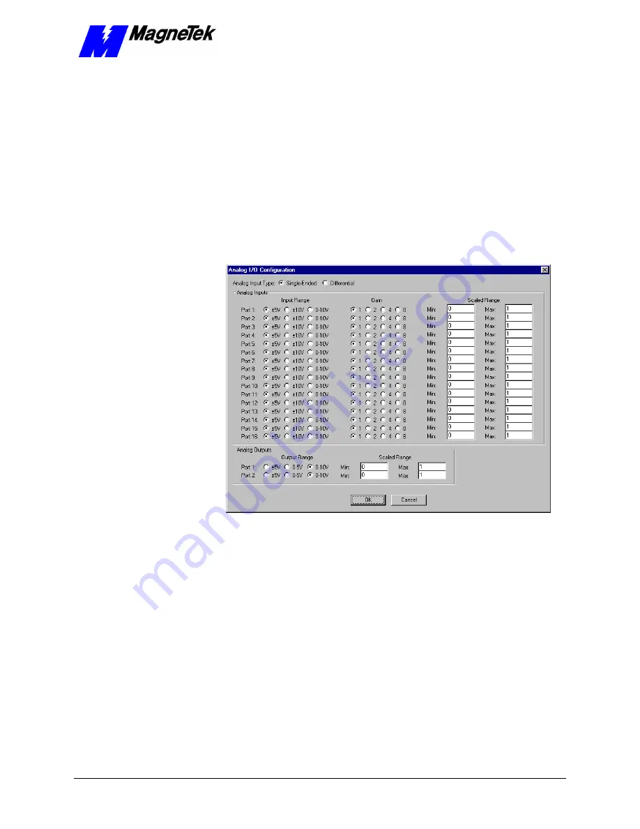
11. Click
Analog I/O
. The
Analog I/O Configuration
screen appears
with
Single-Ended Analog Input Type
selected.
Figure 7.
Analog I/O Configuration screen.
12. You can configure either
Single-Ended
or
Differential
analog input
types. If
Single-Ended
types are selected, all 16 Ports are available. If
Differential
types are selected, 8 Ports are available. Make selections
by clicking the associated radio buttons according to the following
information:
•
For
Input Range
, select one of three possible ranges for each
input signal: +/- 5V; +/- 10V; or 0V to 10V.
•
For
Gain
, select one of four possible gains for each input signal: a
gain of 1, 2, 4 or 8 times.
•
Enter values for the
Scaled Range
of each input. For example, if
the input range is set to +/-5V and the
Scaled Range
is set to
Min
= 0 and
Max
= 1, then the tag will display -5V as 0.0 and +5V
as 1.0. Intermediate values will be scaled proportionately through
this range.


