Flex 6EX System Instruction Manual
March 2016
Page 23 of 38
1
3
2
4
7
5 6
8
8
7
6
5
4
3
2
1
1
234
5
67
8
1
234
5
67
8
RE
LAY FU
NCTI
ON
S
RELAY FUNCTIONS
SYSTEM FUNCTIONS
TEST
JP
7
JP
6
JP
5
JP
4
JP
3
JP
2
JP
1
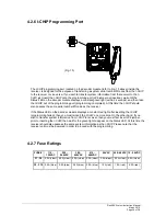
I-CHIP PORT
PB
1 &
PB
2
PB3
& P
B4
PB5 & PB6
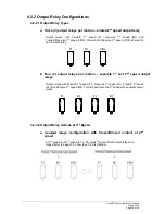
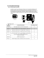
4.2.4 Dip-Switch Settings
4.2.4.1 Interlocked Functions
Interlocked means the two adjacent push buttons cannot be activated simultaneously as
they will cancel each other out. Interlocked settings are usually applied to forward and
reverse motions. Each dip-switch on the decoder module corresponds to one (1) motion or
two (2) adjacent push buttons (refer to Fig. 12 & 13 below). Only the first seven (7) dip-
switch positions are used (counting from left to right); the 8
th
dip-switch position (far right) is
not used.
(Fig. 12)
(Fig. 13)
Manufacture preset
Dip
Settings
Function Descriptions
# of Relays Used
0000000
Normal (single speed only, F2 & R2 relays not used)
2
0000001
Closed/Closed Relay Action at 2
nd
Speed (separate 2
nd
speed relay)
4
0000010
Closed/Closed Relay Action at 2
nd
Speed (shared 2
nd
speed relay)
3
0000011
Opened/Closed Relay Action at 2
nd
Speed (separate 2
nd
speed relay)
4
0001001
On + Start / Off + Start -- Prior to pressing the button you must first rotate
and hold the power key switch at START position to
activate On or Off relays.
2
0001010 FWD/REV
toggled
(latched).
2
0001011
FWD/REV toggled (latched) and affected by the E-stop command.
2

