background image

5275-4 

Remote Record  Reject Operation 

On some units a Record  Reject solenoid  is  mounted  on 

the  changer  sub-plate  (see  Figure  9).  An extension 

of the solenoid piston protrudes through  an opening  in 

OPERATING 

1.

Lift  Balance  Arm  and  swing it out over the  Tone

Arm.

2. Place a quantity of records,  not  exceeding ten,  on

the  record  spindle and  lower them  to the spindle

off-set step.  To insure  proper  indexing,  records

of different sizes must  be stacked with  the  largest

size at the  botto1n.  Be  certain all records are of

the san1e speed.

3. Place  Balance  Arm  over  the records  and select

the correct stylus.

4. Set  Speed  Control  Knob  (Outer  Knob)  to  correct

speed.

NOTE:  This  control  cannot  be  rotated  when the 

On-Off  control is in the  "ON'' position. 

5. Rotate the On-Off Control (Inner Knob) to its  maxi­

mum  clockwise  position  and  release it when  the

turntable  starts  to  revolve.  The Tone Arm will

now  move over and  set  down on the first  record.

To  reject,  rotate  this  control  clockwise  t o  the

"AUTO''  position and release  it.

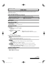
Adapter for  45 RPM  Records 

1. Be sure the On-Off Control Knob is in the "OFF"

position.  P 1 a c e  adapter  over  spindle  witl1 the

the sub-plate and pushes against the striker ar1n on  the 

velocity  trip  mechanism.  T h e   arm  is  then  pushed 

back  by  the  hub projection and unlocks  the main cam 

gear to start the change  cycle. 

INSTRUCTIONS 

arrow on  top  of  spindle pointing towards  the front 

of changer. 

2.

Press  downward  on  a d a p t e r   until  it  is  firmly

seated.  The  arrow will be  pointing to the left  of

center  when the adapter is 

in 

place.

3. To remove the adapter,  pull it straight  up from  tl1e

spindle.

Manual Play 

1.

Lift  the  Record  Balancing  Ar111  and swing it out

over the Tone Arm.

2. Place the record on  turntable spindle.

3. Set  the  Turntable  Speed  Control (Outer Knob)  to

correspond  to  the  type  of  1·ecord  being  played.

Select the  correct stylus.

4. Rotate the On-Off  clockwise to the "ON" position.

5.

Manually  place  the  stylus  gently  on  the  record.

After  the  record  has  been  played,  the tone arn1

will return to its rest lJOsition and the instrument

w i 11  shut-off  auto1natically.  If  only  a  selected

passage is to be played,  the tone arm can  be  lifted

and placed on its rest manually after the passage  is

completed.

STRIKER  ARM 

1  1 

STRIKER  FEED 

LEVER 

1  8 

1  2 

119 

FRICTION  CLUTCH 

ASSEMBLY  - 76130266 

Figure  3--Sub-Plate A·ssembly  with  Cam Gear Re1noved 

Summary of Contents for W602

Page 1: ...triker Arm 121 is fed inward toward the turntable hub by t h e friction of its own weight resting on the curved end of the Striker Feed Lever 111 ISSUED DECEMBER 1966 As the record is playing the Stri...

Page 2: ......

Page 3: ......

Page 4: ...the OFF position P 1 a c e adapter over spindle witl1 the the sub plate andpushesagainst the striker ar1n on the velocity trip mechanism T h e arm is then pushed back by the hub projection and unlocks...

Page 5: ...track is made wider and will set down on a 1 a r g e r d i a m e t e r when the test track is made narrower Since only one half turn of the Adjustment Screw G covers the entire range of the Set Down A...

Page 6: ...Height Adjustment Screw K Figure 5 is used to set the h e i g h t to which the tone arm raises during the change cycle During the change cyclethe tone arm is lifted up and moved out over the rest pos...

Page 7: ...A Resilient Washer 12 is f it t e d b e t w e e n the upper most steel washer and the turntable hub and self aligning dimpled washer is located below the bottom Thrust Washer 4 Make certain that tl1e...

Page 8: ...its n1aximum outward position 6 Insert a sn1all screwdriver between Clutch Boss and top of Sub Plate and raise the entire Clutch Assembly u p w ard on Pivot Tube leaving only approx 005 end play and t...

Page 9: ...Control Knob Replacement NOTE When replacing the Speed Control Knob be sure the bottom pin seats properly into the slot provided for it in the Speed Change Ramp Assem bly 72 Tone Arm Removal and Repl...

Page 10: ...734 2 11 MOLEX RECEPTACLE Late Models Only BLK 01 MFD CHANGER MOTOR BASE PLATE CONTACT PINS 180726 1 Figure 10 142 144 I I I _ I I r 76201010 Y I _V 0 0 I 119 I 0 _ I x A I _ J _ 118 Mute Switch Assem...

Page 11: ...used TURNOVER NEEDLE I V I f l i J z USES TWO NEEDLES TURNOVER NEEDLE ___ USES ONE NEEDLE WITH TWO TIPS I TURNOVER NEEDLE I r I 4 u Gray Body White Body Black Body 1 G USES ONE NEEDLE WITH TWO TIPS S...

Page 12: ...7 I I I 18 u 19 20 1 36 I I I I I I I I I I I I 37 I I I I I 42 I I I I I I I I I SHORT TYPE CONTROL I L ASSEMBLY _J 22 45 I 0 j 43_ i 18 a 44 21 45 e I I 0 49 I tJ 3 22 I I I I I I I I I I I I I J I...

Page 13: ...67 I 1 I I 01 I I I I I 84 e 86 _l 87 I 1 I I I I 79 I 0 81 02 83 88 80 I I 102 50 51 Q 52 53 54 Q 55 56 57 I I I 58 59 84 60 61 85 VO I I 86 I I I 87 62 64 63 89 91 1 145 65 65 1 90 65 2 J 65 3 91 3...

Page 14: ...I I 134 135 136 137 121 120 I 138 I I I I I I I 139 I I I I 107 108 I 130 I I l II I II I I 1 I I I I b I I I I I 0 I I I I I l J I t 140 I I I I I I I I I I I I 141 I 142 0 Figure 14 Exploded View o...

Page 15: ...76204002 76253451 76172501 76201004 76246251 76244009 76252802 76164065 76130118 76211851 76190002 76180074 76250006 76245001 76130266 76246302 76240401 76240101 76528001 76130150 76130147 76250033 76...

Page 16: ...130126 76110057 76130128 76130162 76130126 76110057 170584 1 76130162 76130126 76110057 170584 1 76130162 76130126 76110057 170584 1 76130162 76130126 76110057 170584 1 76130162 76130126 76110057 7613...

Page 17: ...76130142 76110010 603 18 01 170584 1 76130101 76130169 76110010 603 18 02 76130128 76130101 76130169 76110010 603 19 01 170584 1 76130160 76130142 76110010 603 19 02 76130128 76130160 76130142 7611001...

Page 18: ......

Reviews: