


Setting Up the Door/Window Sensors
Your Door/Window Sensors communicate with the Central Controller when an intrusion is detected. To ensure proper opera-
tion of your system, each Sensor sends a signal to the Controller on a regular basis. Your system also lets you know when batter-
ies need to be replaced. These features ensure maximum security protection.
important! Install each Door/Window Sensor one at a time.
Make sure to rubberband the magnets together with the
arrows facing each other before you insert the batteries for that sensor.
DO NOT
put batteries into a Door/Window Sensor
until you are ready to install that particular Sensor. Failure follow these instructions may result in false security zones. you
accidentally separate the magnets while you are installing the Sensor, or if you insert the batteries into all the Door/Window
Sensors at the same time, follow these steps to start over:
1.
Remove batteries from all Door/Window Sensors.
2.
Press the TEST button on each Door/Window Sensor.
3.
Set the Controllers Slider Switch to INSTALL SEC, then press the TEL CODE and MONITOR buttons at the same time.
4.
Follow the steps below to re-install all Sensors:
Uow lets set
up
the Door/Window Sensors.
Attach ONE Door/Window Sensor.
. . . . . . . . . . . . . . . . . . . . . . . . . . . . . . . . . . . . . . . . . . . . . . . . . . . . . . .
a.
b.
Attach the Sensor to the
using the supplied
double-sided tape or screws.
Remove the backing of the double-sided tape on the
Sensors magnets.
C.
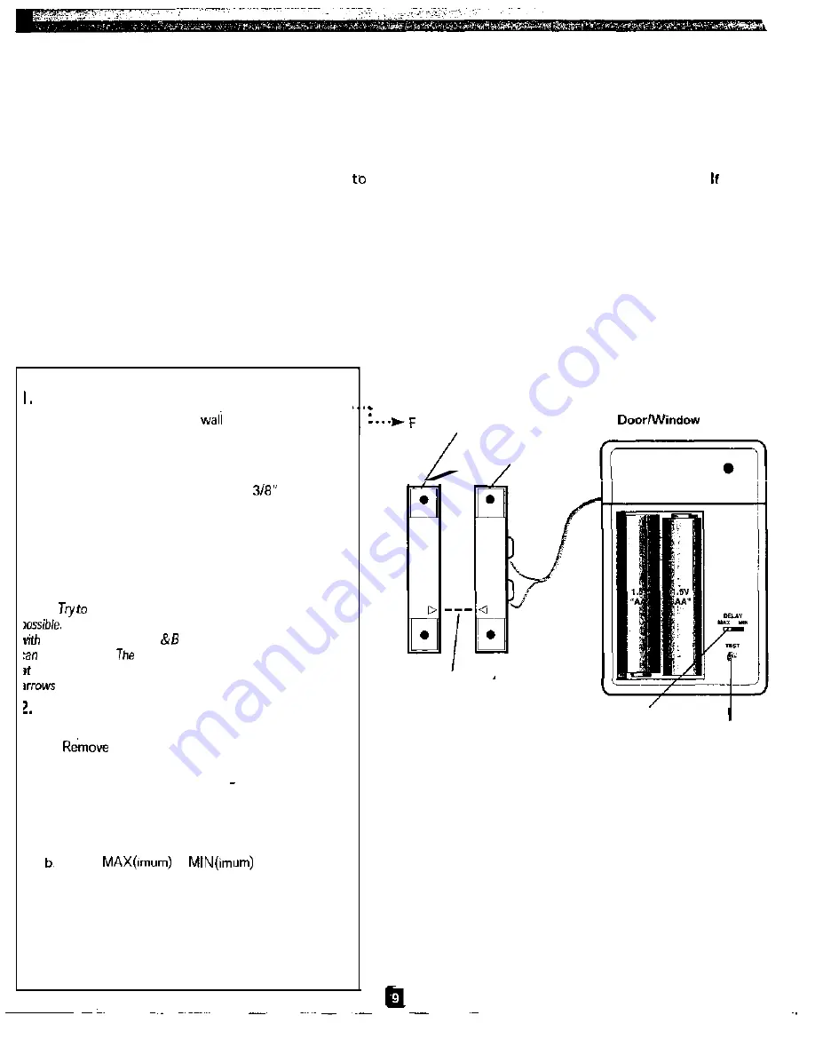
Attach the magnets no more that
apart with
the arrows facing each other:
Place the free-standing magnet on the sliding or
opening part of the window. Place the magnet
attached to the Door/Window Sensor on the frame
of the window or door (adjacent to the free-stand-
ing magnet).
Vote:
match
up the arrows on the magnets as closely as
When
the frame of the door or the
window is
not flush
the
window, Figures A
show
different ways
the
magnets
be positioned.
actual arrows do not have to be pointed
each other. However as Figure
A
shows, the plane that the
are in have to line up.
Insert batteries into ONE Door/Window
Sensor.
. . . . . . . . . . . . . . . . . . . . . . . . . . . . . . . . . . . . . . . . . . . . . . . . . . . . . . .
a.
the battery compartment cover from the
front of the Sensor.
b. insert two AA batteries (+ and sides aligned as
indicated).
3. Set the Delay Switch.
. . . . . . . . . . . . . . . . . . . . . . . . . . . . . . . . . . . . . . . . . . . . . . . . . . . . . .
a. Locate the Delay Switch on the Sensor.
Select
or
to determine
when the Siren will sound after a security breach.
Selecting MIN causes the siren to sound instantly
upon security breach; MAX allows 30 seconds for
entering and 60 seconds for exiting before sounding
the Siren. You may want to select MAX for doors
and MIN for windows.
(continued on next page)
ree-Standing Magnet
Sensor
Door/Window
Sensor Magnet
Arrows Aligned
DELAY switch
TEST button
figure A
SMARTHOME.COM™
1-800-SMART-HOME
949-221-9200
http://www.smarthome.com
Order #7308KIT