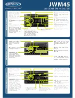
background image

Installing the Unit

1. Using the foam adhesive backer of the remote as

a template, determine the mounting location on

the mounting surface and mark the three hole

locations. 

2. Remove the foam adhesive backer and drill two

3/8" and one 5/8" mounting holes in the marked

positions.

3. Remove the backer to the foam adhesive backer

and adhere it to the back of the remote. 

4. Feed the remote wire through the 5/8" hole in the

mounting surface and attach the remote to the

mounting surface using the supplied screws. 

5. Attach the remote wire to the unit according to

the wiring diagram on Page 11. 

Note: The Wired Remote comes with an extension

cord so the remote can be mounted a far distance

from the receiver. 

This unit is a wired remote control made using a modified controller or similar layout. It is capable of

operating the specified functions on the M6100CD receiver. The body, buttons, controls and display are

UV and water-resistant. It includes a LCD and an illumination circuit.

Take a moment to read through this section and become familiar with the operations and features of this

outstanding product. It is advisable to keep this manual in your vehicle so it is readily available for refer-

ence. Be sure to fill out and send in your warranty card to ensure that you receive the full benefits of war-

ranty repair in the unlikely event that your system will need service.

Waterproof Wired Remote Introduction

Installation Procedures

8

Mounting Surface

Foam Adhesive 
Backer

Mounting Surface

Mark & Drill Holes

Screws

Wire to Unit

Mounting Surface

Summary of Contents for M6100CD

Page 1: ...nd CD Stereo Receiver EJECT ELAPSE SHIFT POWER MARINE CD RECEIVER PULL OPEN 4 X 50W REMOTE VOLUME MAIN VOLUME DISP BAND TRK TUNE MUTE 5 INT 4 RDM 3 RPT 2 PGM 1 MEM TRK TUNE SEL MODE AS PS SCAN CH SHIF...

Page 2: ...entertainment system Introduction 1 Power Turns the unit On Off 2 Dimmer Loud Button Loud Button Enhances high frequency and low frequency sound quality Dimmer Button Press and hold this button to cha...

Page 3: ...djusts the Volume of the remote secondary set of speakers 14 Shift and Scan Button Shift Changes the Track Tune Buttons 5 to Track Up and Track Down See CD Changer Operations for more information Scan...

Page 4: ...n 15 for more than 2 sec onds the radio will then search the current fre quency and check the signal strength until the five strongest stations are stored into the correspond ing preset number button...

Page 5: ...elected station frequency In CD Mode When the display priority is set to Time the time will be displayed Pressing DISP button will temporarily display time CD track number time remaining or elapsed ti...

Page 6: ...ks Use the Program function to select up to 32 CD tracks to play in any order The Program function allows you to select a track number for each spot in the playing sequence A CD must be inserted to us...

Page 7: ...the button 4 to pause the CD CDC player Press it again to resume play 5 Volume Buttons Press the button to in crease or the button decrease the volume level 6 Manual Search Tuning and Track Selection...

Page 8: ...ar distance from the receiver This unit is a wired remote control made using a modified controller or similar layout It is capable of operating the specified functions on the M6100CD receiver The body...

Page 9: ...gative terminal or wire Green Wire Connect this wire to the Left Remote Speaker positive terminal or wire Green Wire with Black Stripe Connect this wire to the Left Remote Speaker negative terminal or...

Page 10: ...Wire with Black Stripe Right Main Speaker Right Remote Speaker Power Antenna Switched 12v out Blue Wire Ground B Black Wire Yellow Wire Red Wire Battery 12v in Ignition Switch 12v in Antenna Socket Re...

Page 11: ...me Auxiliary Audio Input RCA with Yellow Cables Red RCA Right CD Changer Connection M6100CD CD Changer Optional 8 Pin Din Connector Male to Male 8 Pin Din Cable Supplied with CD changer Wired Remote C...

Page 12: ...tching area on the tem plate Then drill four 1 8 mounting holes in the exact position according to the mounting paper 3 Use the glue paper to stick the two mounting brackets to the back of the mountin...

Page 13: ...olume to the desired level Speaker wiring is not properly connected Check the wiring connection Sound skips The installation angle is more Adjust the installation angle to less than 30 degrees than 30...

Page 14: ...damage to the products result ing from improper installation alteration accident misuse abuse or acts of nature MAGNADYNE CORPORATION OR ITS AUTHORIZED AGENTS SHALL NOT BE LIABLE TO ANYONE FOR CONSEQU...

Page 15: ...Copyright 2003 Magnadyne Corporation M6100CDUM Rev A 11 03 A Registered Trademark of Magnadyne Corporation...

Reviews: