BLUEPIRAT2 | USER MANUAL/
page 80 of 82
17
List of figures
Figure 4.1: links to the manuals in the System Client ............................................................... 10
Figure 5.1: Interface (overview) ................................................................................................ 13
Figure 6.1: Front side of the BLUEPIRAT2 ............................................................................... 15
Figure 6.2: Front side of the BLUEPIRAT2 5E .......................................................................... 15
Figure 7.1: Power connection of the BLUEPIRAT2 ................................................................... 24
Figure 7.2: Power connection of the BLUEPIRAT2 5E ............................................................. 24
Figure 7.3: Switching on ........................................................................................................... 24
Figure 7.4: Info screen IP address ............................................................................................ 25
Figure 7.5: Change IP settings ................................................................................................. 26
Figure 7.6: Client Portal ............................................................................................................ 27
Figure 7.7: Desktop icon ........................................................................................................... 28
Figure 7.8: Content of the portable client .................................................................................. 28
Figure 7.9: Rear side of the BLUEPIRAT2 with MOST150 ....................................................... 29
Figure 7.10: Rear side of the data logger BLUEPIRAT2 5E MOST150 ..................................... 30
Figure 7.11: new power supply connector with reverse polarity protection................................ 30
Figure 8.1: Sampling interval .................................................................................................... 31
Figure 8.2: Setting triggers using digital Input ........................................................................... 32
Figure 14.1: Rear side BLUEPIRAT2_14C6S8L ....................................................................... 55
Figure 14.2: Rear side BLUEPIRAT2_25M24C8LFR ............................................................... 55
Figure 14.3: Rear side BLUEPIRAT2_150M14C8LFR ............................................................. 55
Figure 14.4: Connecting the BLUEPIRAT2 via the universal adapter cable .............................. 56
Figure 14.5: Power cable for BLUEPIRAT2 5E ......................................................................... 59
Figure 14.6: RS232/digital/analog adapter cable ...................................................................... 60
Figure 14.7: Listening to a bidirectional serial communication .................................................. 60
Figure 14.8: Adapter cables for digital/analog ........................................................................... 62
Figure 14.9: Ethernet kit for BLUEPIRAT2................................................................................ 63
Figure 14.10: Pinout of RJ45 Ethernet connectors ................................................................... 64
Figure 14.11: Adapter cables for FlexRay................................................................................. 65
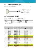
Figure 14.12: Adapter cables for CAN/FlexRay ........................................................................ 66
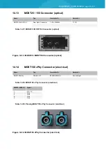
Figure 14.13: MOST25 / MOST150 Connector (optical) ........................................................... 68
Figure 14.14: MOST150 cPhy Connector (electrical) ................................................................ 68
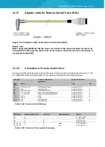
Figure 14.15: Adapter cable for Remote Control Voice (RCV) .................................................. 69
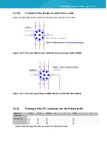
Figure 14.16: Pins des DIN-Steckers DIN-Steckers (Lumberg SV81-8 DIN8) ........................... 70
Figure 14.17: Pins des gewinkelten LEMO-Steckers (FGH.1B.308.CLAD42) ........................... 70
Figure 15.1: OTRS Ticket system ............................................................................................. 74
Figure 15.2: .............................................................................................................................. 75

