Page 14 of 14
507860-01
Issue 1927
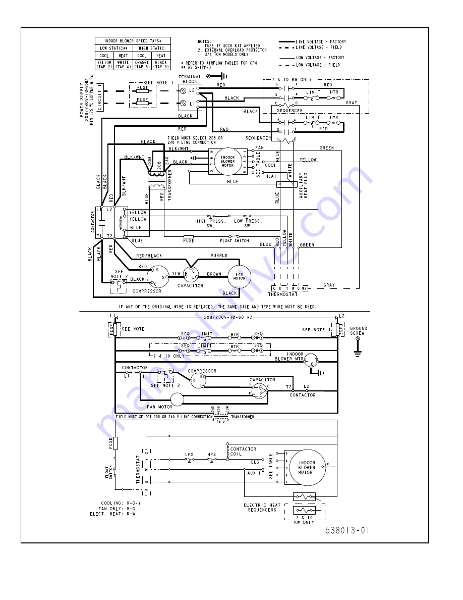
Figure 10. Connection Diagram - MCE With Factory Installed Electric Heater
# 538013-01
Page 1: ...nd any state or provincial laws or local ordinances Local authorities having jurisdiction should be consulted before installation is made Such applicable regulations or requirements take precedence ov...
Page 2: ...ated airflow requirements ofANSI ASHRAE 193 complies with IECC 2015 are identified on the rating plate Installation and servicing of air conditioning equipment can be hazardous due to internal refrige...
Page 3: ...g a door or access panel opposite the front of the unit is the preferred method of providing access The door or access panel must be at least 30 wide centered on the unit and as tall as the unit IMPOR...
Page 4: ...ille Installation Refer to installation instructions included with the wall sleeve kit and the louver grille kit along with Figure 2 for guidance in assembling and installing the wall sleeve and louve...
Page 5: ...on to top and bottom corners of unit to sleeve seal Caulk if needed Ductwork Ductwork should be designed and sized according to the methods in Manual Q of the Air Conditioning Contractors of America A...
Page 6: ...0 08 475 68 0 09 440 73 0 10 400 77 0 10 5 kW TAP 4 HEAT 525 59 0 08 505 65 0 09 480 69 0 09 N A N A N A N A N A N A TAP 5 HEAT 615 81 0 11 590 88 0 12 560 94 0 13 530 99 0 13 500 103 0 14 MCE4 11 181...
Page 7: ...HEAT 740 65 0 09 705 74 0 10 640 83 0 11 N A N A N A N A N A N A TAP 5 HEAT 820 81 0 11 790 91 0 12 740 100 0 13 675 109 0 15 600 117 0 16 7 kW TAP 4 HEAT 860 91 0 12 835 100 0 13 795 108 0 14 N A N A...
Page 8: ...er Model Number Filter Area in2 MCE4 11 09 MCE4 11 12 250 0MCE4 11 18 3MCE4 11 18 5MCE4 11 18 310 7MCE4 11 18 10MCE4 11 18 380 MCE4 11 24 420 MCE4 11 30 480 MCE4 11 36 575 Table 5 Minimum Required Sur...
Page 9: ...xtures or appliances Follow manufacturer s instructions enclosed with the thermostat for general installation procedures Color coded insulated wires 18 AWG should be used to connect the thermostat to...
Page 10: ...wer up to unit there is a 3 minute time delay to the compressor contactor R to Y Any 24V interrupt R C to the defrost control will initiate the 3 minute delay to the contactor Cooling When the thermos...
Page 11: ...1P Extruded Aluminum Louver Kit 33 Height ALVRAL 2 Extruded Aluminum Louver Kit Custom Color 33 Height ALVRAL 2P Extruded Aluminum Louver Kit 45 Height ALVRAL 3 Extruded Aluminum Louver Kit Custom Co...
Page 12: ...Louver ASLEEVE8 2 8 32 3 4 16 16 5 8 32 7 8 for 45 Louver ASLEEVE8 5 8 45 16 16 5 8 45 1 8 10 Wall Sleeve Kit for 29 Louver ASLEEVE10 1 10 29 16 16 5 8 29 1 8 for 33 Louver ASLEEVE10 2 10 32 3 4 16 16...
Page 13: ...507860 01 Issue 1927 Page 13 of 14 Figure 9 Connection Diagram MCE Without Electric Heater 538012 01 Wiring Diagrams...
Page 14: ...Page 14 of 14 507860 01 Issue 1927 Figure 10 Connection Diagram MCE With Factory Installed Electric Heater 538013 01...