


ES
FR
EN
IT
28
Madas Technical Manual
- 9|9.4 - REV. 0 of 8
th
Feb 2019
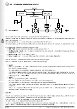
MTC10
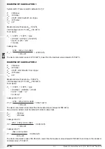
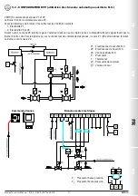
EXAMPLE OF CALCULATION 1
System with 1 Pressure switch calibrated to P
i
/2
P
i
: 200 mbar
P
set
: 100 mbar
V
p
: 2 EVP... DN 50 with 20 cm of pipe
P
atm
: 1013 mbar
t
test
: 20"
Maximum burner flow rate Q
max
: 60 m
3
/h
Limit leakage rate (0.1% of Q
max
): 60 dm
3
/h
Test volume:
V
p
= ½ EVP... + ½ EVP... + pipe
= (0.95/2) + (0.95/2) + (0.2x2.85)
= 0.475 + 0.475 + 0.57
= 1.52 dm
3
Leakage rate:
(200 – 100) x 1.52 x 3600
V
1.2
= = 27.00 dm
3
/h
1013 x 20
The device can detect a leak of 27.00 dm
3
/h, lower than the maximum value allowed of 60 dm
3
/h.
EXAMPLE OF CALCULATION 2
P
i
: 250 mbar
P
set
: 125 mbar
V
p
: 2 EVP... DN 100 with 10 cm of pipe
P
atm
: 1013 mbar
t
test
: 20"
Maximum burner flow rate Q
max
: 500 m
3
/h
Limit leakage rate (0.1% of Q
max
): 500 dm
3
/h
Test volume:
V
p
= ½ EVP... + ½ EVP... + pipe
= (6.494/2) + (6.494/2) + (0.3x9)
= 3.247 + 3.247 + 2.7
= 9.194 dm
3
Leakage rate V1,2 :
(250 – 125) x 9.194 x 3600
V1,2 = = 204.21 dm
3
/h
1013 x 20
The device can detect a leak lower than the maximum value allowed of 500 dm
3
/h.
Two pressure switches must be installed to detect a lower leak.
P
set1
: 50 mbar
P
set2
: 200 mbar
Leakage rate V2 :
(250 – 200) x 9.194 x 3600
V2 = = 88.08 dm
3
/h
1013 x 20
Leakage rate V1 :
(50) x 9.194 x 3600
V1 = = 88.08 dm
3
/h
1013 x 20
The device can detect a leak of 88.08 dm
3
/h, lower than the maximum value allowed of 500 dm
3
/h and close to the standard
minimum value of 50 dm
3
/h.


