


Macurco
TM
Macurco RD-24 Manual
REV
–
1.0.0
[34-8708-4770-1]
9
|
P a g e
4
Operations
4.1
Power up
Power LED will light up green to indicate the unit is operational. TX LED will flash blue to indicate the unit is communicating.
Slot 1, Slot 2, Slot 3 and Slot 4 will light up green when corresponding relay is activated/populated. Refer to Figure 3-3 above for
location of Slot 1-4.
4.2
Initial Operating Mode
4.2.1
RD-24 Settings
The DIP switches are used to set the Modbus address and are also used to change the communication settings. Valid Modbus
addresses for RD-24 are from 193 to 200 where switch 1 is the least significant bit (LSB) and switch 8 is the most significant bit
(MSB). Address 254 is used to place the RD-24 in programming mode. Address 255 is used to refresh the configuration of the
RD-24.
4.2.2
Programming Mode
When the RD-24 is powered with address set to 254, it enters programming mode. The STATUS LED will be flashing RED and
GREEN alternatively every 200 milliseconds to indicate that RD-24 is ready and waiting for the user to enter new communication
settings using 8 dip switches. Using the 8 dip switches, the user can change the communication settings like baud rate and
parity.
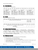
When looking at the switches with “Address” marking on top, the switches are defined from left to right.
•
Switch 8, switch 7 and switch 6 are used to modify baud rate
•
Switch 5 and switch 4 are used to modify parity
•
Switch 1 is used to request to save the new settings
•
Switches 3 and 2 are unused and should be left in the ON position.
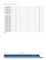
Switch 8
Switch 7
Switch 6
Description
OFF
OFF
OFF
Default Value (19200 Bd)
OFF
OFF
ON
4800 Bd
OFF
ON
OFF
9600Bd
OFF
ON
ON
19200 Bd (Default value)
ON
OFF
OFF
38400 Bd
ON
OFF
ON
57600 Bd
ON
ON
OFF
115200 Bd
ON
ON
ON
Do not change
Table 4-1
–
Baud Rate Configuration


