


Macurco
TM
Macurco RD-24 Manual
REV
–
1.0.0
[34-8708-4770-1]
14
|
P a g e
Figure 4-6
–
Zone 4-20mA Output Mode Menu
4.3.1.3
Configure 4-20mA Input or Analog Input
Analog Inputs read gas sensors connected to RD-24 and will work the same as digital sensors readings, which
are the sensors with MRS-485 connected to DVP-1200 through the RS-485 network using the Modbus
protocol.
Sensors connected to RD-24 should be displayed to the
user as “RD
-
24 #address.#analog_input”.
#analog_input has a range from 1 to 16, as each RD-24 can have up to 4 expansion boards connected, and
each analog input expansion board has 4 analog inputs.
DVP-1200 has the capability to connect to up to 192 sensors. By default, DVP-1200 is configured to connect
to 192 digital sensors.
Each RD-24 that is discovered by DVP-1200 and has analog inputs will cause the controller to internally map
the RD-24 analog inputs to one of the 192 sensors and automatically adjust the limit of digital sensors that
can be connected to the controller.
The sensor mapping will be done from top to bottom. It grows from sensor #192 all the way to 128.
By default, DVP-1200 allocates space to connect to 192 digital sensors. If an RD-24 with analog inputs is
connected to the controller, DVP-1200 will automatically allocate sensor addresses from the list of 192 in the
following order:
-
The first RD-24 connected to DVP-1200 will occupy sensor addresses 177 thru 192 in order and as needed.
For example: Slot 1, input 1 will occupy address 177 and Slot 4, input 4 will occupy address 192.
-
The second RD-24 connected to DVP-1200 will occupy sensor addresses 161 thru 176 in order and as
needed.
-
The third RD-24 connected to DVP-1200 will occupy sensor addresses 145 thru 160 in order and as needed
-
The fourth RD-24 connected to DVP-1200 will occupy sensor addresses 129 thru 144 in order and as needed
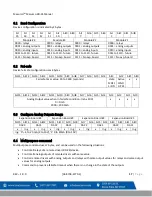
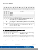
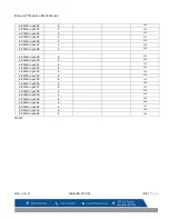
NOTE
: The addresses have been allocated to the exact locations as described
–
they do not change based on
the
number of analog input expansion boards installed into any number of RD-24 units. For a full list of
addresses and slot designations, see “Remote Device I/O Chart” below.


