


12G-SDI FMC Card
12
Getting Started - 12G-SDI FMC Card
©Macnica, Inc.
5.
Hardware Setup
The following shows the procedure for setting up the hardware.
1.
Attach a jumper cap to JP2-2 and JP2-3 on the FMC card.
2.
Attach a jumper cap to JP4-2 and JP4-3 on the FMC card.
3.
Connect the FMC card to FMC Port B (J2) on the Arria 10 GX FPGA Development Board.
4.
Connect the AC adaptor provided to the 12-V DC input (J13).
5.
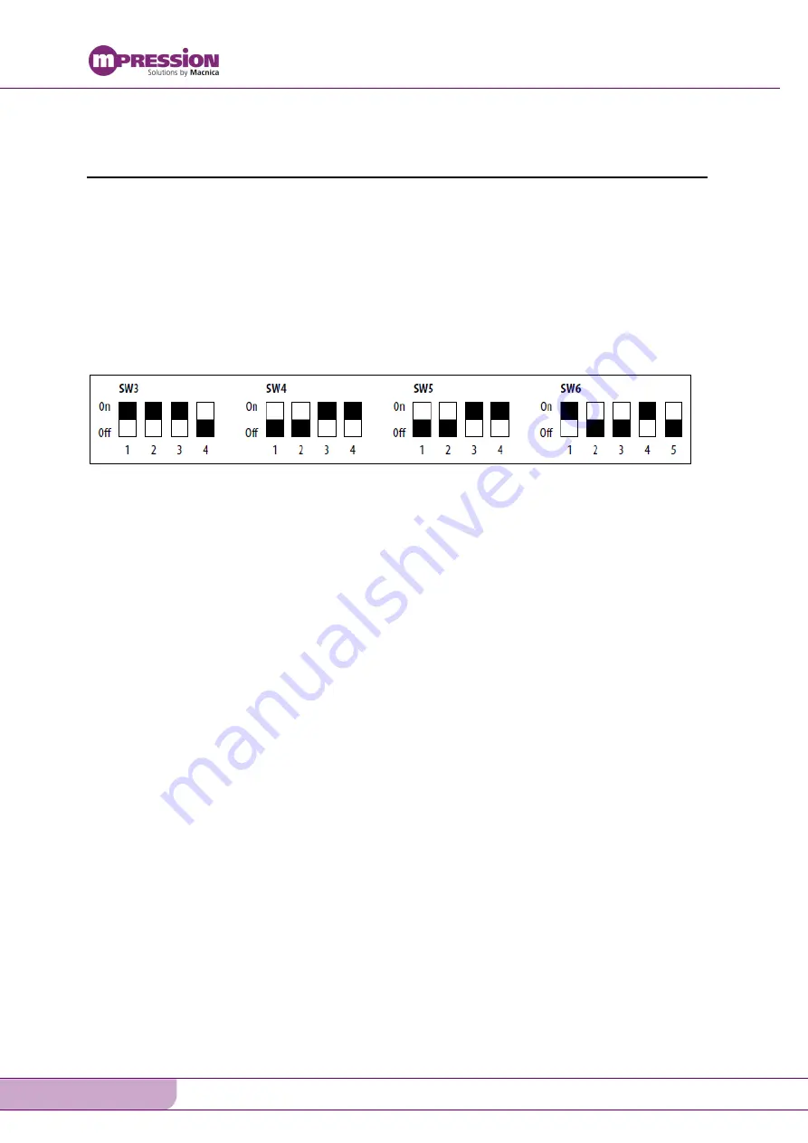
Set the DIP switches (SW3, SW4, SW5, and SW6) on the Arria 10 GX FPGA Development Board
as shown in Figure 5-1.
6.
Use a BNC cable to connect the 12G-
SDI signal generator’s output terminal to CN8 on the FMC
card.
7.
Use a BNC cable to connect the 12G-
SDI monitor’s input terminal to CN4 on the FMC card.
Figure 5-1. Arria 10 GX FPGA Development Board DIP Settings
(The ■ indicates the side to which the switch has been slid)


