background image

Owner's Manual   

11

well as to solo, and add to aux send 1-4. This is routed 
using the FW/line input selector [23] on channels 15 
and 16. This is useful for live performances, where 
those 2 channels might have, for example, a software 
synthesizer you are triggering from a MIDI keyboard, 
and you want to treat the softsynth as "just another 
instrument," with equal processing and routing    
options as the hardware keyboards coming into the 
other channels.

The FireWire interface works with both PC (using 

ASIO for Windows XP and Vista) and Mac (Core Audio 
for Mac OS 10.4.11 or higher).

4. LEFT/RIGHT XLR MAIN OUTPUTS

These male XLR connectors provide a balanced  

line-level signal that represents the end of the mixer 
chain, where your fully mixed stereo signal enters the 
real world. Connect these to the inputs of your main 
power amplifiers, powered speakers, or serial effects 
processor (like a graphic equalizer or compressor/ 
limiter). It provides a fully balanced signal that is the 
same level as the 1/4" TRS main out jacks [13] on the 
top panel.

5. MAIN OUTPUT LEVEL

When this switch is out (+4 dB), the XLR main 

outputs [4] provide a "+4 dBu" line-level signal. You 
can then connect these outputs to the line-level inputs 
of power amplifiers, powered loudspeakers, or serial 
processors.

When the switch is pushed in (mic), the XLR main 

outputs are attenuated to microphone level. You can 
then connect these outputs safely to the microphone  
inputs of another mixer, providing a submix for  


keyboards or drums, for example, in a live sound  
application. The main outputs can then be plugged  
directly into a stage snake, and appear back at the front 
of house console like any other microphone level source.

When mic is engaged, you can safely plug the 
XLR main output into a mixer's microphone 
input, even if it provides 48 V phantom power.

The switch is recessed, to reduce the chance of    

accidently turning it on or off when plugging things in.

6. AUX SENDS 1-4

These 1/4" TRS connectors allow you to send balanced 

or unbalanced line-level outputs to external effects 
devices, headphone amplifiers, or stage monitors. These 
could either be passive stage monitors powered by an 
external amplifier, or powered stage monitors with  
built-in power amplifiers. All aux sends are independent 
of each other, so you can set up to four separate aux 
mixes. The overall aux output level can be adjusted with 
the aux send master controls [45].

The aux sends can either be pre or post fader,  

depending on the position of the pre/post switches [46]. 
For stage monitor work, use pre, so the stage monitors 
do not increase in volume when the channel faders are 
adjusted. Imagine how upsetting that can be to big hairy 
drummers. This allows you to set up the monitor mix 
and levels just right, and not have it change every time a 
channel fader is adjusted.

For external processors, use post. In this way, the feed 

to external processors will vary with the channel faders, 
so the level of any returned effect (like an echo) will 
also change if the channel fader is changed, keeping 
them in the same ratio (wet/dry).

7. AUX RETURNS 1-4

These 1/4" TRS stereo input connectors allow you to 

add the stereo processed output from external effects 
processors or other devices to the main mix.

Level adjustment of the incoming signals is made with 

the aux return controls [47].

The signals going into aux return 3 can also be added 

to aux send 1 by engaging the return to aux 1 switch 
[48]. For example, you could add effects from an  
external effects processor to your stage monitors.

You can also use these inputs to add any stereo  

line-level signals to your main mix, so it could be  
another line-level source, not just an effects processor.

If you are connecting a mono source, use the left 

(mono) aux return input, and the mono signals will  
appear on both sides of the main mix.

8. INSERT (Ch. 1-8)

These unbalanced 1/4" jacks on channels 1-8, are for 

connecting serial  effects processors such as  
compressors, equalizers, de-essers, or filters. The insert 
point is after the gain control [21] and low cut filter 
[19], but before the channel’s EQ and fader [35]. 
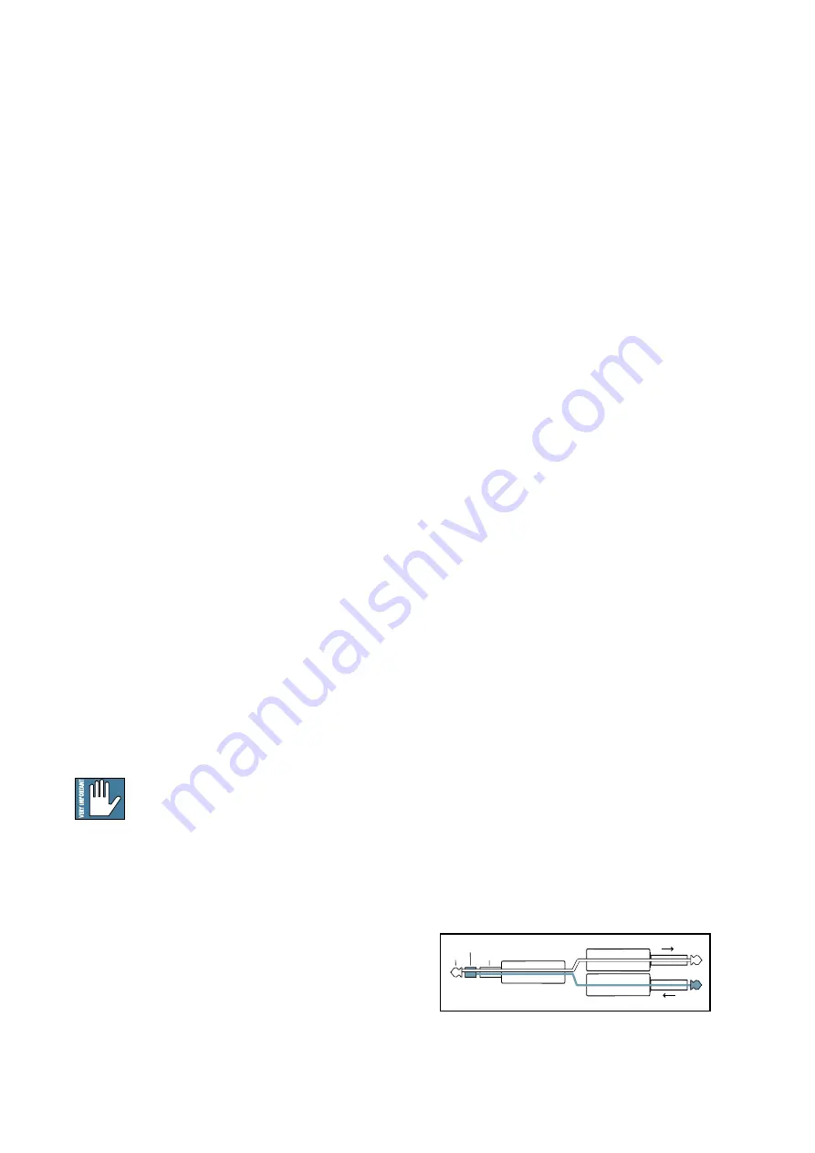
The channel signal can go out of the insert jack to an 
external device, be processed (or whatever) and come 
back in on the same insert jack. To do this requires a 
standard insert cable that must be wired thusly:

Tip = send (output to effects device)
Ring = return (input from effects device)
Sleeve = common ground

“tip”

This plug connects to one of the 

mixer’s Channel Insert jacks.

“ring”

tip

ring

sleeve

SEND to processor

RETURN from processor

(TRS plug)

Summary of Contents for Onyx 1620i

Page 1: ...S MANUAL 16 Channel Premium Analog Mixer with FireWire SOLO SOLO SOLO SOLO SOLO SOLO SOLO SOLO SOLO SOLO SOLO SOLO MUTE MUTE MUTE MUTE MUTE MUTE MUTE MUTE MUTE MUTE MUTE MUTE 48V 48V 48V 48V 48V 48V 4...

Page 2: ...he Canadian Department of Communications ATTENTION Le pr sent appareil num rique n met pas de bruits radio lectriques d passant las limites applicables aux appareils num riques de class A de class B s...

Page 3: ...l when making connections pressing solo or doing anything that may cause loudness in the headphones This will help protect your hearing Always turn down the main mix level and control room level when...

Page 4: ...With aux sends 1 and 2 routable to your DAW the 1620i allows you to use your favorite plug in as a realtime effect Just route an aux send to your DAW apply the plug in and assign your DAW outputs to...

Page 5: ...infor mation that is critically important or unique to the mixer For your own good read them and remember them This icon will lead you to some explanations of features and practical tips Go ahead and...

Page 6: ...26 HIGH MID EQ LEVEL CH 1 8 18 27 LOW MID EQ FREQUENCY CH 1 8 18 28 LOW MID EQ LEVEL CH 1 8 18 29 MID EQ LEVEL CH 9 16 18 30 LOW EQ 18 31 AUX SENDS 1 4 19 32 PAN 19 33 MUTE SWITCH AND ALT 3 4 19 34 20...

Page 7: ...d to monitor levels The club is driven by connecting a pair of HD1801 powered subwoofers and a pair of HD1531 powered speakers to the main left and right outputs A laptop computer connects to a FireWi...

Page 8: ...input from the aux 4 send and its stereo outputs connect to the stereo return inputs A desktop computer connects to a FireWire port allowing the 2 channel main mix individual channels and the aux send...

Page 9: ...ng in the control room A desktop Mac or PC is connected to a FireWire port allowing the 2 channel main mix to be recorded and two channels to be played back Two cinema screens are connected to the des...

Page 10: ...This will reduce the possibilities of any turn on or turn off thumps in your speakers 3 FIREWIRE CONNECTIONS FireWire is a high speed two way interface for connecting digital devices Two FireWire con...

Page 11: ...mplifier or powered stage monitors with built in power amplifiers All aux sends are independent of each other so you can set up to four separate aux mixes The overall aux output level can be adjusted...

Page 12: ...ug wired as follows Tip Positive or hot Sleeve Shield or ground Insert jacks continued Insert jacks can be used as channel direct outputs post gain and pre EQ See the connector section on page 28 figu...

Page 13: ...2 track FireWire feed from your computer if FW 1 2 is selected A combination of all four above Except for main mix whatever is playing in these outputs can also be routed to the main mix if assign to...

Page 14: ...main mix and it is affected by the main mix level 55 The output could also be used as an extra set of main outputs for feeding another zone 17 HEADPHONE OUTPUT This 1 4 TRS connector supplies the outp...

Page 15: ...nd line level The 4 band EQ has shelving high shelving low and peaking hi mid and peaking lo mid with adjustable mid frequency Stereo Channels 9 16 The stereo channels each have two line level inputs...

Page 16: ...he cord 19 LOW CUT Ch 1 8 only The mono channels each have a low cut switch often referred to as a high pass filter that cuts bass frequencies below 75 Hz at a rate of 18 dB per octave The low cut swi...

Page 17: ...ubtly and use the left sides of the knobs cut as well as the right boost If you find yourself repeatedly using a lot of boost or cut consider altering the sound source such as placing a mic differentl...

Page 18: ...ar sound are almost always found within this range For example the female vocal range as well as the fundamentals and harmonics of many higher timbred instruments 27 LOW MID EQ FREQUENCY Ch 1 8 This k...

Page 19: ...ake the sound appear much louder when panned center 33 MUTE switch and ALT 3 4 The dual purpose mute alt 3 4 switch is a Mackie signature When Greg was designing our first product he had to include a...

Page 20: ...er a solo switch is engaged you will only hear the soloed channel s in the headphones and control room This gives you the opportunity to audition the channels before they are added to the main mix or...

Page 21: ...he control room and phones outputs to prevent feedback 3 If you have tape as your source matrix selection and then engage this switch it can create a feedback path between tape in and tape out Make su...

Page 22: ...way down before connecting headphones or pressing a solo switch 36 or doing anything new that may affect the headphone volume Then turn it up slowly as you listen carefully 42 LEFT RIGHT Level Meters...

Page 23: ...d turn the knob down but that never happens The aux sends are also sent to FireWire output 15 and 16 for recording The levels to FireWire are affected by these send controls and the pre post switch 4...

Page 24: ...engage assign to main mix You can even use the computer as two separate independent mono in stereo out processors Have aux 1 go into one plug in and aux 2 go into a different one The stereo outputs of...

Page 25: ...you the ultimate feeling of power and control over the sound levels sent to your audience If you press the main mix switch 37 you can see the main mix levels in the meters 42 Adjust this control care...

Page 26: ...t in case one of your external pieces has a problem Make sure that you are not overdriving your amplifiers Check the loudspeaker average load impedance is not less than the minimum your amplifier can...

Page 27: ...ug is connected tip to signal send output from mixer ring to signal return input back into mixer and sleeve to ground earth 1 4 TS Phone Plugs and Jacks TS stands for Tip Sleeve the two connections av...

Page 28: ...on its merry way through the mixer This allows you to tap out the channel signal without interrupting normal operation If you push the 1 4 TS plug in to the second click you will open the jack switch...

Page 29: ...te 0 5 dB 20 Hz to 20k 3 dB at 45 kHz Distortion THD N 20 Hz to 20 kHz 20 Hz to 80 kHz bandwidth Mic input at insert 4 dBu in 0 dB gain 4 dBu out 0 0057 Mic input at insert 36 dBu in 40 dB gain 4 dBu...

Page 30: ...rove our products by incorporating new and improved materials components and manufacturing methods Therefore we reserve the right to change these specifications at any time without notice Mackie and t...

Page 31: ...sum Aux Returns 2 and 4 are identical Aux sends C R dim to FW out Firewire I O 16 Mic 0 60dB Line 20 40dB Firewire outputs NOTE Switches are shown in the default out position HPF 75 Hz Low Cut bypass...

Page 32: ...the world oh so much better Procedure 1 Turn off the mixer and disconnect all cords 2 Place the mixer face up on a soft and dry flat surface 3 Remove the eight silver screws as shown below and hand t...

Page 33: ...this owner s manual you will not be reading this yet Its a bit of a paradox really because didn t you just read it Like this bit of text right now Hmm MackieWindowsFireWireAudioDriver InstallationInst...

Page 34: ...dio applications such as iTunes or Windows Media Player InstallationforWindowsXP 1 Connect the FireWire cable from your Onyx 1620i to the computer 2 Power on your Onyx 1620i 3 The Windows XP applicati...

Page 35: ...he new software has been installed successfully and that the found new hardware wizard is complete 11 Pack yourself a big lunch and go for a nice walk outside Have a picnic and lie back and dream Thin...

Page 36: ...lick Audio MIDI Setup 4 Click the Audio Devices tab and select Onyx i in the Properties For drop down box 5 Here you can see the settings for the mixer You can also choose it as your default input or...

Page 37: ...insert but the circuit board can be modified so that they are post insert instead For example this allows for the use of an external processor on the mic signal sending the result to the FireWire whi...

Page 38: ...38 Onyx 1620i Onyx 1620i Track Sheet SOLO SOLO SOLO SOLO SOLO SOLO SOLO SOLO SOLO SOLO SOLO SOLO MUTE MUTE MUTE MUTE MUTE MUTE MUTE MUTE MUTE MUTE MUTE MUTE 48V 48V 48V 48V 48V 48V 48V 48V...

Page 39: ...presentative will at its option either repair or replace any such nonconforming product provided that Customer gives notice of the noncompliance within the Warranty Period to the Company at www mackie...

Page 40: ...Road NE Woodinville WA 98072 USA United States and Canada 800 898 3211 Europe Asia Central and South America 425 487 4333 Middle East and Africa 31 20 654 4000 Fax 425 487 4337 www mackie com E mail s...

Reviews: