background image

6

Corner or Center Placement

Placing the subwoofer in a corner (corner 

loading) excites the most room modes in the 
room, which tends to smooth the individual 
peaks and dips caused by each standing wave. 
Moving the subwoofer outward from the corner 
along the wall results in fewer standing waves, 
but may result in noticeable peaks at certain 
frequencies.

Some people prefer to place the subwoofer 

between the left and right main speakers, so 
that all the sound is coming from the same 
plane. Some prefer to use two subwoofers and 
place one with the left speaker and the other 
with the right speaker. The Master Out/Slave 
In connections on the HRS10 allow you to do 
this quite easily. 

Another benefit of corner placement is 

increased efficiency and lower distortion. The 
energy that is reflected off the walls reinforces 
the direct sound, putting less of a demand on 
the power amplifier to reach higher sound 
pressure levels.

It is important that the corner has good 

structural strength, or the low-frequency en-
ergy can cause rattling and other distracting 
vibrations.

Experiment with the orientation of the 

subwoofer. The driver in the HRS10 faces 
downward toward the floor while the passive 
radiator faces out the front. In some cases, 
the subwoofer may sound better with the pas-
sive radiator facing toward the wall. It may be 
helpful to play steady-state tones or pink noise 
while a partner moves the subwoofer (perhaps 
on a small wheeled cart), to make it easier to 
hear the differences in the sound as the changes 
in placement and orientation are made.

Principle of Reciprocity

One trick that has been used successfully to 

find the best location for a subwoofer is placing 
the subwoofer in your listening position. The 
principle of reciprocity says that you can find 
the best location for the subwoofer by switching 
places between the listening position and the 
subwoofer position. It is important that the 
cabinet be raised off the ground and at the same 
level as your ears. If that’s not possible, at least 
put the subwoofer in the same location as your 
listening position to achieve a close approximation.

PLACEMENT

AN IMPORTANT NOTE 

ON HRS120 BASS 

RESPONSE AND YOUR 

CONTROL ROOM OR 

LISTENING ROOM

  You’ve heard it before. “Low-frequencies are 
non-directional, so it doesn’t matter where you 
place the subwoofer.” Although it is true that fre-
quencies below about 100Hz are non-directional, 
it is also true that a lot of factors can conspire 
to thwart the HRS10’s extended low frequency 
— including room shape, room volume, and 
 acoustical treatment. 

This is not a cop-out or an apology. It’s plain 

old physics in action. Here are some tips to help 
you find the best placement for your HRS10 
and optimize the low-frequency response in 
your particular room. Consider the following:

Room acoustics and bass-handling ability

Nobody likes to buy a subwoofer and a new 

set of speakers and then be told that they 
should spend extra bucks on bass traps or a re-
modeling job. But the simple fact is, “standard” 
rooms, i.e. rectangular rooms in conventional 
business or residential structures, are rarely if 
ever conducive to optimal low bass reproduc-
tion without some modifications.

However, understanding what can cause 

degradation of the low-frequency response in 
a room can help in choosing a location that can 
minimize the problems associated with poor 
bass response—most notably interference and 
resonance.

Interference is caused when the reflected 

wave from the surrounding walls arrive out-of-
phase with the direct sound. This can weaken 
or even cancel the sound. Keeping the distance 
between the subwoofer driver and any adjacent 
walls no longer than 1/8 of a wavelength (0 in. 
or 51 cm at 80Hz) can minimize interference.

Room resonance is caused by the reinforce-

ment of certain frequencies between 0Hz and 
00Hz, which creates “standing waves” or room 
modes. These resonant frequencies are deter-
mined by the dimensions of the room. The bass 
response is sharply boosted for a narrow band 
near resonance, and then appears to be attenu-
ated between resonances.

Summary of Contents for HRS120

Page 1: ...URE ARE REGISTERED TRADEMARKSOF MACKIE DESIGNS INC THX PM3 AND LUCASFILM ARE TRADEMARKS OF LUCASFILM LTD USED BY PERMISSION S M SLAVE MASTER SLAVE IN INPUT OUTPUT INPUT OUTPUT MASTER OUT LEFT IN OUT R...

Page 2: ...F ELECTRIC SHOCK DO NOT OPEN RISQUE DE CHOC ELECTRIQUE NE PAS OUVRIR CAUTION TO REDUCE THE RISK OF ELECTRIC SHOCK DO NOT REMOVE COVER OR BACK NO USER SERVICEABLE PARTS INSIDE REFER SERVICING TO QUALIF...

Page 3: ...nd HR624 meets all THX requirements for mixing and monitoring multi channel programs Inordertoachieveaseamlessintegrationbetween the subwoofer and the main speakers in the system speaker placement is...

Page 4: ...you really know what they do For now just leave all the switches out and the CROSSOVER controls set to the center position 80Hz For stereo applications 1 Connect the left and right line level signal...

Page 5: ...POWER ON POLARITY N A LFE GAIN SUBSONIC FILTER SUBSONIC FILTER CROSSOVER CONTROLS FILTER SELECT FILTER BYPASS STANDARD SETTINGS NORMAL 80Hz SUB SAT INPUT SENSITIVITY THX PM3 SETTINGS POLARITY LFE GAIN...

Page 6: ...netberaisedoffthegroundandatthesame level asyourears Ifthat snotpossible atleast putthe subwoofer in the same location as your listening position to achieve a close approximation PLACEMENT AN IMPORTAN...

Page 7: ...ubwoofer first and any other powered speakers in the system to prevent thumps and other noises generated by any upstream equipment from coming out the speakers When power ing up turn on the powered sp...

Page 8: ...SENSITIVITY control is in the NORMAL position Refer to the QUICK START section on page 4 for the level setting procedure This is where you connect your signal in puts and outputs to the subwoofer and...

Page 9: ...uthebestsound LEFT AND RIGHT INPUTS Balanced XLR female and unbalanced RCA female connectors are provided for the left and right inputs Connect the full range line level signal from the mixer or pream...

Page 10: ...ofer is bypassed An internal relay closes shorting the tip and sleeve of the REMOTE INDICA TOR jack whenever the subwoofer is in bypass mode either triggered manually with the FOOT SWITCH or by the au...

Page 11: ...SS FILTER IN FULL RANGE SUB 110Hz 55Hz 80Hz SAT CROSSOVER SUB 110Hz 55Hz 80Hz SAT MONO POWER POWER SUB BYPASSED DESIGNED BY MACKOIDS IN WOODINVILLE WA USA 2001 MACKIE DESIGNS INC ALL RIGHTS RESERVED P...

Page 12: ...ng You should use high quality shielded cable to connect the signal source to the LEFT and RIGHT IN and OUT jacks on the HRS120 Foil shielded cables such as Belden 8451 8761 or 9501 are commonly used...

Page 13: ...e hum Is there a light dimmer or other triac based SCR device on the same AC circuit as the monitor Dimmers cause buzzing noises Use an AC line filter or plug the subwoofer into a different AC circuit...

Page 14: ...e com click Support and select Locate a Service Center Service for Mackie products living outside the United States can be obtained through local dealers or distributors If you do not have access to o...

Page 15: ...SLAVE INPUT SUBWOOFER BYPASS FOOTSWITCH NOTE WHEN USED AS A SLAVE THE MASTER OUTPUT OF THE FIRST SUB DRIVES THIS INPUT POLARITY AND INPUT SENSITIVITY ONLY ARE ACTIVE ON THIS INPUT OPEN HPF FROM CROSSO...

Page 16: ...Thermal Protection Heatsink and Power Transformer temperature auto reset Amplifier Section Rated power output 1 THD 100 Hz 400 watts rms into rated 8 load Burst power output 100 Hz sine with 10 duty...

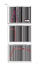
Page 17: ...Crossover Filter Response 40 10 38 36 34 32 30 28 26 24 22 20 18 16 14 12 10 8 6 4 2 0 2 4 6 8 dBr 20 20k 50 100 200 500 1k 2k 5k 10k Hz HRS120 Elliptical Filter Response 40 10 38 36 34 32 30 28 26 24...

Page 18: ...r of files A Hewlett Packard LaserJet 5000N with a duplex tray installed to save trees was used to print out laser proofs PDF files were created with Acrobat Distiller 4 0 A wind driven open window pr...

Page 19: ...e under warranty Note You must have a sales receipt from an authorized Mackie dealer for your unit to be considered for warranty repair IMPORTANT Make sure that the Service Request Number is plainly w...

Page 20: ...Road NE Woodinville WA 98072 USA United States and Canada 800 898 3211 Europe Asia Central and South America 425 487 4333 Middle East and Africa 31 20 654 4000 Fax 425 487 4337 www mackie com E mail s...

Reviews: