DRM P
rofes
sional P
ow
er
ed L
oudspeak
er S
eries
10
DRM Professional Powered Loudspeaker Series
DRM Loudspeakers: Rear Panel Features
1. Power Connection
This is a standard 3-prong IEC power connector.
Connect the detachable power cord (included in
the packaging with the loudspeaker) to the power
receptacle, and plug the other end of the power
cord into an AC outlet.
Make sure that the AC power is matched to
the AC power indicated on the rear panel
(below the IEC receptacle).
Disconnecting the plug’s ground pin is
dangerous. Don’t do it!
2. Power Switch
Press the top of this rocker switch inwards to turn
on the loudspeaker. Press the bottom of this rocker
switch inwards to turn off the loudspeaker.
As a general guide, the mixer (or other
signal source) should be turned on first,
subwoofers next, and loudspeakers last.
As such, the loudspeakers should also be turned
off first, followed by the subwoofers, then the mixer.
This will reduce the possibility of any turn-on or
turn-off thumps and other noises generated by any
upstream equipment from coming out of the speakers.
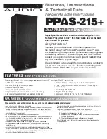
3. XLR and 1/4" Combo Inputs [Ch. 1 and 2]
Input channels 1 and 2 may accept a balanced
mic signal using an XLR connector. They are wired
as follows, according to standards specified by
the AES (Audio Engineering Society).
XLR Balanced Wiring:
Pin 1 = Shield (ground)
Pin 2 = Positive (+ or hot)
Pin 3 = Negative (– or cold)
In addition to accepting a balanced mic signal
using an XLR connector, these input channels may
also accept 1/4" line-level signals driven by balanced
or unbalanced sources.
2
3
1
SHIELD
COLD
HOT
SHIELD
COLD
HOT
3
2
1
Also, channel 2 may accept a Hi-Z source (such
as a guitar) via the 1/4" input without the need for
a separate DI box. Be sure to set the Ch. 2 In to Hi-Z in
the Configuration menu, though! Directions on page 17.
To connect balanced lines to these inputs, use
a 1/4" Tip-Ring-Sleeve (TRS) plug. “TRS” stands
for Tip-Ring-Sleeve, the three connection points
available on a stereo 1/4" or balanced phone jack
or plug. TRS jacks and plugs are used for balanced
signals and are wired as follows:
1/4" TRS Balanced Mono Wiring:
Sleeve = Shield
Tip = Hot (+)
Ring = Cold (–)
SLEEVE
TIP
SLEEVE
TIP
RING
RING
TIP
SLEEVE
RING
50-60 Hz 110W
100-240VAC
PUSH FOR SETTINGS
MAX
OFF
MIX OUT
DIRECT OUT
DIRECT OUT
INPUT
INPUT
SPEAKER CONTROL
GAIN
GAIN
INPUT
GAIN
LINE
MIC
U
+50dB
OFF
LINE
MIC
+50dB
OFF
U
1
3
6
4
7
5
8
10
9
2