background image

4

BIG KNOB

BIG KNOB

Introduction

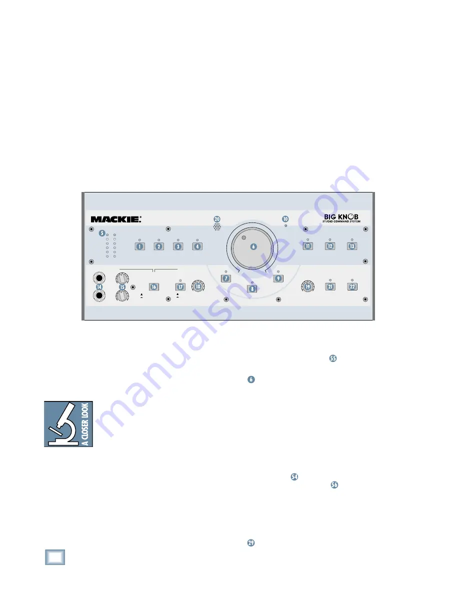
Thank you for choosing the Mackie Big Knob, 

your signal routing and monitoring solution for your 
DAW-based studio. Big Knob provides a control 
room matrix and the basic features of an expensive 
mixer, but tailored for the requirements of your 
DAW (Digital Audio Workstation) environment. 
These features include selecting up to four separate 
stereo input sources, monitoring through three dif-
ferent speakers for A/B/C comparisons, providing a 
separate headphone mix and a studio output for the 
talent, and a built-in talkback mic for slate-to-tape 
and headphone cueing. In other words, it gives you 
everything you need from a mixer, without the stuff 
you don’t need!

Another important feature you’ve come to expect 

from Mackie is pristine sound quality, and Big Knob 
is no exception. This is studio-quality gear, and we 
made sure the audio signal suffers no degradation 
by passing through Big Knob. You can connect this 
baby between your expensive DAW and your 

really


expensive studio monitors with no reservations. 
Big Knob will pass the test!

Big Knob is part of the growing family of Mackie 

computer recording products. Visit our website 
(www.mackie.com) to learn more about these prod-
ucts and the solutions to your audio and recording 
needs that Mackie has to offer, or pick up a catalog 
at your nearest Mackie dealer.

INPUT SOURCE(S)
PHONES MIX INPUT

OFF
ON

POWER

POWER

MUTE

DIM

MONO

MIC

TO

PHONES/

STUDIO

TO

2-TRACKS

LEVEL

LEVEL

1

O

O

MAX

O

O

MAX

2

O

O

MAX

O

O

MAX

TALKBACK

STUDIO OUTS

INPUT SOURCE SELECT

PHONES/

STUDIO OUTS

SOURCE

DAW

MIX

2-TRACK

A

2-TRACK

B

PHONO

MONITOR SELECT

A

B

C

OL

8

0

4

8

24

INPUT

PHONES

0 = +4dBu

VOLUME

MAX

O

O

Getting Started

The following steps will help you set up your Big 
Knob and get the levels adjusted correctly. Once you 
have made the connections and adjustments, refer to 
the Features section for more in-depth information 
about each input, output, switch, and control knob.

Most of the inputs and outputs on Big Knob 
have either a trim control or a level switch 
labeled –10 dB and +4 dB. This actually 
comes from two standard operating levels 
that have evolved in the audio industry: 
–10 dBV consumer level and +4 dBu pro-

fessional level. Most consumer equipment with RCA 
connectors operate at the –10 dBV level, while most 
professional equipment with 1/4-inch phone jacks 
or XLR connectors operate at the +4 dBu level. 
As you might expect, the +4 dBu level is higher 
(louder) than the –10 dBV level, so it is important to 
match the input and output levels of Big Knob to the 
equipment you have connected to it. For a Big Knob 
input, the –10 dB setting accepts a smaller signal 
and provides more gain than the +4 dB setting. For 
a Big Knob output, the –10 dB setting produces a 
smaller signal than the +4 dB setting.

Zero the Controls

1.  Turn off the POWER switch

on the rear panel.

2.  On the front panel, turn the Big VOLUME Knob

and all the LEVEL controls all the way down 

(counterclockwise).

3.  Set all the switches to the up position (front 

and rear panels).

4.  On the rear panel, turn all the trim controls all 

the way down (counterclockwise).

Connections

1.  Connect the supplied detachable power cord to 

the AC socket

on the rear panel of Big Knob. 

Set the AC SELECT switch

 to the correct 

position that corresponds to the AC voltage you 
are using (100-120V or 220-240V).

For Monitoring:

2.  Connect the audio outputs (stereo mix) from 

your DAW’s audio interface to the two DAW MIX

input jacks on the rear panel of Big Knob.

Summary of Contents for BIGK NOB

Page 1: ...POWER POWER MUTE DIM MONO TO PHONES STUDIO TO 2 TRACKS LEVEL LEVEL 1 O O MAX O O MAX 2 O O MAX O O MAX TALKBACK STUDIO OUTS INPUT SOURCE SELECT PHONES STUDIO OUTS SOURCE DAW MIX 2 TRACK A 2 TRACK B PH...

Page 2: ...ety and Health Administration OSHA has specified the permissible noise level exposures shown in the following chart According to OSHA any exposure in excess of these permissible limits could result in...

Page 3: ...ing 13 Repair 14 AppendixB Connections 15 XLRConnectors 15 1 4 TRSPhonePlugsandJacks 15 1 4 TSPhonePlugsandJacks 15 RCAPlugsandJacks 15 FootswitchPlugandJack 15 AppendixC TechnicalInfo 16 BigKnobSpeci...

Page 4: ...8 24 INPUT PHONES 0 4dBu VOLUME MAX O O GettingStarted The following steps will help you set up your Big Knob and get the levels adjusted correctly Once you have made the connections and adjustments...

Page 5: ...ctive speakers and headphone amplifiers 3 Start playback on your DAW and play some thing you ve already recorded or a demo track You want to be able to listen to it over the moni tor speakers connecte...

Page 6: ...e STUDIO OUTS jacks is in the 10 dB position counterclockwise If it is turn the control up to the 4 dB position and then turn up the LEVEL control Now it should get louder faster 12 If you have a head...

Page 7: ...ACK inputs creating a circular loop that results in a terrible howl You must remember to turn off the 2 TRACK INPUT SOURCE SELECT button when recording to your 2 track recorder DAW MIX Turns on the si...

Page 8: ...f the PHONES STUDIO OUT SOURCE switch described below PHONES 1 and 2 Level Control These rotary knobs control the volume of the stereo signal at the PHONES 1 and 2 headphone connec tors The same signa...

Page 9: ...TRACK B output connectors DAW output connectors TO PHONES STUDIO Pressing this momentary button illuminates the red LED above the button activates the internal talk back MIC and sends its signal to t...

Page 10: ...you to precisely fine tune the incoming level of the DAW MIX input so it matches the signal level of other incoming 2 track sources PHONO These stereo RCA unbalanced inputs are fed by the outputs of a...

Page 11: ...ecessary to precisely match the levels among the MONITOR A B and C outputs MONITOR B OUTPUTS Works as described above for the Monitor A path MONITOR B Trim Control Works as described above for the Mon...

Page 12: ...to an amplifier and passive monitors in the studio per formance space This allows the performers to hear playback without having to use headphones and allows the control room engineer to communicate...

Page 13: ...them one by one When the noise goes away you ll know which input source is causing the problem Sometimes it helps to plug all the audio equip ment into the same AC circuit so they share a common groun...

Page 14: ...nsible for any damage that occurs due to non factory packaging 5 Include a legible note stating your name ship ping address no P O boxes daytime phone number RA number and a detailed description of th...

Page 15: ...d Tip Hot FootswitchPlugandJack The TALKBACK FOOTSWITCH jack accepts a 1 4 TS plug Shorting the tip and sleeve together activates the talkback circuit This is equivalent to pressing the TO 2 TRACKS an...

Page 16: ...Muted Level Off 90 dB 1 kHz Trim Control Range Input Trim Controls Center Detented 10 dB Output Trim Controls 14 dB to 0 dB Dim Switch 0 dB 20 dB Rated Input Voltage Line Inputs 4 dB Level Setting 4 d...

Page 17: ...s and are hereby acknowledged 2004 LOUD Technologies Inc All Rights Reserved INPUT SOURCE S PHONES MIX INPUT OFF ON POWER POWER MUTE DIM MONO MIC TO PHONES STUDIO TO 2 TRACKS LEVEL LEVEL 1 O O MAX O O...

Page 18: ...NPUT L R L MONO RIAA RIAA TRIM TRIM VDC VDC OFF ON TRIM VDC OFF ON TRIM VOLUME VDC DIM 0 dB 20 dB VDC OFF ON OFF ON R L MONO R L MONO R 4 10 dBV 4 10 dBV 4 10 dBV 10 10 10 10 10 10 10 10 VDC VDC VDC O...

Page 19: ...d in the Service section of this manual 5 Contact the Authorized Mackie Service Center to arrange service or bring the Mackie product to them F LOUD Technologies and Authorized Mackie Service Centers...

Page 20: ...16220 Wood Red Road NE Woodinville WA 98072 USA US and Canada 800 258 6883 Europe Asia Central and South America 425 487 4333 Middle East and Africa 31 20 654 4000 Fax 425 487 4337 www mackie com E m...

Reviews: