background image

Summary of Changes

At MacDon, we

re continuously making improvements, and occasionally these improvements affect product

documentation. The following list provides an account of major changes from the previous version of this document.

Section

Summary of Change

Internal Use Only

Revised instruction format to include front and back covers, and
safety section.

Tech Pubs

2 Parts List, page 5

Revised parts illustration to make it easier to distinguish between
the left and the right sensor assemblies.

Support

3 Installation Instructions, page 7

Added steps and illustration for identifying the left and right
sensor assemblies.

Added note to ensure the connector is facing down and the
sensor arm arrow is facing the combine.

Added step to ensure the rubber boot is attached to the cable
adjuster nut.

Reordered steps so that the harness gets fully installed before
securing. After the harness is installed, and it gets secured
from the float indicator box and working down to the sensor.

Added step to set the float and wing balance before calibrating
the AHHC system.

Added note that if the combine sees the center sensor (except
John Deere), then connector C40 on the FM100 main harness
is not connected.

Added photos taken during an install to help clarify the
procedure.

Support

4.1 Manually Checking
Voltage Range

Two-Sensor

System, page 17

4.2 Adjusting Voltage Limits

Two-Sensor System, page

21

4.3 Sensor Output Voltage
Range

Combine

Requirements, page 24

Added Troubleshooting topics.

Support

214143

ii

Revision F

Summary of Contents for FM100

Page 1: ...FM100 Float Module Dual Sensor Auto Header Height Control AHHC Kit MD B6211 Installation Instructions 214143 Revision F Original Instruction The Harvesting Specialists...

Page 2: ...is based on the information available and in effect at the time of printing MacDon Industries Ltd makes no representation or warranty of any kind whether expressed or implied with respect to the info...

Page 3: ...ation time for this kit is 1 5 hours Conventions The following conventions are used in this document Right and left are determined from the operator s position The front of the float module is the sid...

Page 4: ...tor is facing down and the sensor arm arrow is facing the combine Added step to ensure the rubber boot is attached to the cable adjuster nut Reordered steps so that the harness gets fully installed be...

Page 5: ...1 1 2 General Safety 2 Chapter 2 Parts List 5 Chapter 3 Installation Instructions 7 Chapter 4 Troubleshooting 17 4 1 Manually Checking Voltage Range Two Sensor System 17 4 2 Adjusting Voltage Limits...

Page 6: ......

Page 7: ...if not avoided will result in death or serious injury WARNING Indicates a potentially hazardous situation that if not avoided could result in death or serious injury It may also be used to alert agai...

Page 8: ...e glasses or goggles Heavy gloves Wet weather gear Respirator or filter mask 1000005 Figure 1 2 Safety Equipment Be aware that exposure to loud noises can cause hearing impairment or loss Wear suitabl...

Page 9: ...machine function and or safety It may also shorten the machine s life To avoid injury or death from unexpected startup of the machine ALWAYS stop the engine and remove the key from the ignition before...

Page 10: ......

Page 11: ...OR LINK 2 4 276201 HARNESS LH HEIGHT SENSOR 1 5 276871 HARNESS RH HEIGHT SENSOR 1 6 136410 CLAMP INSULATED 3 8 IN 2 7 136655 FASTENER FIR TREE MT W TIE 4 A 135671 BOLT HEX HD TFL M6 X 1 X 40 8 8 A2L 2...

Page 12: ......

Page 13: ...ity The kit is installed with the float module attached to the header 2 Shut down the combine and remove the key from the ignition IMPORTANT Before installing the sensor assemblies make sure you corre...

Page 14: ...not sold separately 1030467 A B C A Figure 3 3 Installing Sensor Link Bracket 5 Install sensor link bracket A MD 295179 arms into hole B at the top of the float lever with the indented end of the bra...

Page 15: ...s not twisted and then fully tighten bolt C 1024211 A B Figure 3 5 Right Sensor Assembly 10 Check if jam nuts A are tight against the two ball joints of the right sensor assembly If jam nuts are not s...

Page 16: ...l the right sensor assembly A onto the rear of the float module frame as shown with bolts B on the assembly slotted into place on the frame Make sure the sensor connector faces down 1030474 A B C Figu...

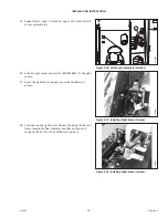
Page 17: ...ight Sensor Harness 16 Connect right sensor harness A MD 276871 to the right sensor 17 Route the right sensor harness up inside the frame as shown 1030480 A B C Figure 3 12 Installing Right Sensor Har...

Page 18: ...xisting clamp that secures the float indicator cable to the frame NOTE Do NOT route the float indicator cable through clamp B 1030542 A B Figure 3 14 Securing Right Sensor Harness 20 Secure the right...

Page 19: ...igure 3 17 Installing Left Sensor Harness 23 Route left sensor harness A up inside the frame as shown between the frame and hydraulic hoses B 1030534 A B Figure 3 18 FM100 Main Harness P537 24 Near th...

Page 20: ...the FM100 main harness 1030538 A Figure 3 20 Securing Left Sensor Harness 26 Secure the top end of the left sensor harness to the inside frame using fastener A MD 136655 1030539 A B Figure 3 21 Securi...

Page 21: ...t the cable tie at plug C45B B on the completion harness b Disconnect connector C45A from plug C45B B c Near the selector valve manifold locate connector C40 A on the FM100 main harness and remove the...

Page 22: ...or system 29 Before calibrating the AHHC system set float and wing balance A light float will affect AHHC calibration and system performance For instructions refer to the header operator s manual 30 F...

Page 23: ...e adjusting the sensors verify the sensor arms are properly installed on the sensors Left Sensor A The point on the arm of the sensor should face away from the header The point on the float sensor arm...

Page 24: ...oth locations NOTE If the header is not on down stops during the next two steps the voltage may go out of range during operation causing a malfunction of the AHHC system 1027026 B A Figure 4 3 Float I...

Page 25: ...float module side frame Ensure it is at the high voltage limit for the combine NOTE The wiring harness connector must be attached to the sensor Do NOT disconnect it 8 Repeat at the opposite side 10161...

Page 26: ...ure it is at the low voltage limit for the combine NOTE The wiring harness connector must be attached to the sensor Do NOT disconnect it 11 If the sensor voltage is not within the low and high limits...

Page 27: ...C D 1 Before adjusting the sensors verify the sensor arms are properly installed on the sensors Left Sensor A The point on the arm of the sensor should face away from the header The point on the float...

Page 28: ...Kit Left Sensor 4 Loosen sensor mounting nuts A 5 Check that the left sensor is at the correct high voltage limit 6 Rotate sensor B counterclockwise to lower the voltage Rotate sensor clockwise to rai...

Page 29: ...er the voltage Rotate sensor counterclockwise to raise the voltage 12 Check that the right sensor is at the correct high voltage limit 13 Tighten sensor mounting nuts A 1016102 A Figure 4 11 Float Ind...

Page 30: ...9230 and 7240 8240 9240 0 5 V 4 5 V 2 5 V Case IH 2588 2577 2 8 V 7 2 V 4 0 V Challenger Gleaner A Massey Ferguson and IDEAL Series 0 5 V 4 5 V 2 5 V CLAAS 500 600 700 Series 0 5 V 4 5 V 2 5 V Gleane...

Page 31: ......

Page 32: ...16 891 7313 f 816 891 7323 LLC MacDon Russia Ltd 123317 Moscow Russia 10 Presnenskaya nab Block C Floor 5 Office No 534 Regus Business Centre t 7 495 775 6971 f 7 495 967 7600 MacDon Australia Pty Ltd...

Reviews: