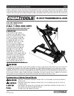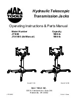


ASSEMBLY
(Refer to figure 1 & 2)
1. Three major parts should be included in package:
(a) Hydraulic unit with pumping mechanism ( with
air motor equipped for Model JTA1000),
(b) Saddle unit, and
(c) 2 pieces of base half with bolts and washers.
2. Attach either one of the two base halves to the base
of the hydraulic unit, then secure using allen head
bolts and washers provided. Then apply the same
procedure to the other base half. Use torque wrench
to tighten to 30 lb.ft.. Do not overtighten.
3. Position the saddle unit above the ram piston, place
the saddle socket onto the ram piston. Secure using
the set screw.
4
BEFORE USE
1. Inspect jack before each use. Do not use if bent,
broken or cracked components are noted. Ensure that
casters move freely. Check for and tighten any loose
assemblies.
2. Verify that the product and the application are
compatible.
3. Press the release valve, ensure that saddle is fully
lowered. Remove shipping screw and replace with vent
screw. (shipping screw is on top of the oil filler screw)
4. Ensure oil level is just below the rim of the oil filler
screw hole.
Air Actuated Jacks only (JTA1000)
1. Pour a teaspoon of good quality air tool lubricant into
the air supply inlet (See Figure 2). Connect to air
supply and operate for 3 seconds to evenly distribute
lubricant.
2. Air actuated product is fitted to accept the popular
1/4" NPT air nipple. When installing air nipple, ensure
that thread tape or compound is used on connections.
Do not allow compound to enter the air supply inlet
orifice. Application of thread tape is acceptable, but
ensure that it is not applied beyond the first machine
thread.
OPERATION
Raise saddle:
Caution!
For model JTA1000, do not operate the jack
by pumping the lift pedal and air pump pedal at the same
time.
1. Pump foot pedal or press air pump pedal (Model
JTA1000) until saddle reaches desired position.
2. Follow vehicle manufacturer's recommended
procedures for removing the load as outlined in
vehicle service manual or repair guide.
3. Secure load with provided chains. Ensure load's
center of gravity is centered on the saddle and load
is stable before moving jack.
Lower saddle:
Important!
Be sure all tools and personnel are clear
before lowering load.
Slowly, gently apply downward pressure to the release
valve pedal.
•
Study, understand, and follow all printed materials
provided with/on this product before use.
•
Do not exceed rated capacity.
•
Use only on hard, level surfaces capable of
supporting rated capacity loads.
•
Use of this jack is limited to the removal,
installation and transportation of transmissions,
transfer cases and transaxles. Do not use a
transmission jack to tilt or support a vehicle.
•
Ensure that center gravity of load is centered on
the saddle.
•
Do not exceed 10
0
tilt angle of the saddle
assembly in all directions.
•
Adequately support the vehicle before starting
repairs.
•
Use only chains provided.
•
If loaded jack must be moved, make sure that the
load is secured, stable and in lowest position.
•
This is a lifting and lowering device only.
•
Transfer load immediately to appropriate support
device for service or repair.
•
No alterations shall be made to this product.
•
Failure to heed these markings may result in
personal injury and/or property damage.
!
WARNING
To avoid crushing and related
injuries:
NEVER work on, under or
around a load supported only
by a jack. Immediately
transfer the load to an
appropriate work station.
!
WARNING