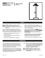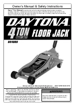


Air Pump
Saddle
Assembly
Lift pedal
Position Handle
Shipping/
Vent Screw
(not shown)
Oil Filler Screw
(not shown)
Base Halves
Swivel Caster
Reservoir
Tilt Adjustment
Knobs
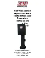
Air Pump Pedal
Release Valve
Air Supply Inlet
(not shown)
* Air/ Lever Actuated Model
3
Save these instructions.
For your safety, read and understand the information contained within. The owner and
operator shall have an understanding of this product and safe operating procedures before attempting to use this
product. Instructions and Safety information shall be conveyed in the operators native language before use of this
product is authorized. Make certain that the operator thoroughly understands the inherent dangers associated with the
use and misuse of the product. If any doubt exists as to the safe and proper use of this product as outlined in this
factory authorized manual, remove from service until which time it is clear.
Inspect before each use.
Do not use if
broken, bent, cracked or otherwise damaged parts are noted. If the jack has been or suspected to have been subjected
to a shock load, discontinue use until checked out by an authorized factory service center. Owners and operators of
this equipment shall be aware that the use and subsequent repair of this equipment may require special training and
knowledge. It is recommended that an annual inspection be done by qualified personnel and that any missing or
damaged parts, decals, warning / safety labels or signs be replaced with authorized replacement parts only. Any jack
that appears to be damaged in any way, operates abnormally or is missing parts, shall be removed from service
immediately until such time as repairs can be made.
PRODUCT DESCRIPTION
Mac Tools Hydraulic Telescopic Transmission Jacks are designed to be used as an aid in the removal and installation
of vehicle component parts and assemblies, specifically transmissions. They are for use under an overhead lift or in a
garage pit. The air actuated function is an added feature on Model JTA1000. Ensure that your air source can dedicate
7.8 CFM @ 90 - 175PSI to each jack operated. To ensure dependable, troublefree operation an air dryer and oiler is
recommended.
SPECIFICATIONS
Capacity
77 5/8"
Model
Min. Height
Max. Height
37 7/8"
JT1000
Base Size ( L x W )
1000 Lbs
JTA1000*
1000 Lbs
37 7/8"
77 5/8"
34 1/8" x 35 1/2"
34 1/8" x 36 1/8"
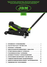
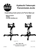
Figure 1 - Model JT1000 Components
Figure 2 - Model JTA1000 Components
Note:
Vent Screw and Oil Filler Screw are located on the upper portion of the reservoir.
See exploded drawing on page 6 & 7
Chain
Release Valve
Lift Pedal
Saddle
Assembly
Tilt Adjustment
Knobs
Position Handle
Shipping/
Vent Screw
(not shown)
Oil Filler Screw
(not shown)
Swivel Caster
Base Halves
Reservoir
Chain