background image

I

NSTALL


THE

 S

ERVER


S

TEP

 4: G

ENERATE

 SSL C

ERTIFICATE

52

M86 S

ECURITY

 I

NSTALLATION

 G

UIDE

Step 4: Generate SSL Certificate

Generate a Self-Signed Certificate for TAR

This step requires you to generate a self-signed certificate for the Threat Analysis 
Reporter to ensure secure exchanges between the appliance and your browser.

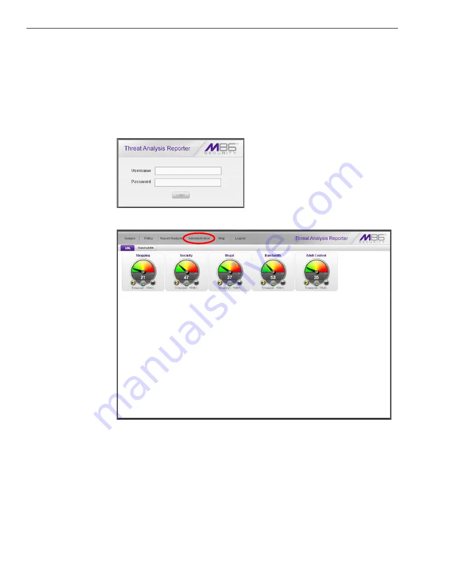
A. In the Threat Analysis Reporter login window, type in the 

Username 

and 

Pass-

word

 registered for the TAR Wizard:

B. Click 

Login

 to display the gauges dashboard of the TAR user interface:

C. Go to the navigation menu bar at the top of the screen and select 

Administra-

tion > Device Registry

 to display the Device Registry screen:

Summary of Contents for HL

Page 1: ...M86 Threat Analysis Reporter INSTALLATION GUIDE Models HL SL MSA Software Version 2 1 10 Document Version 06 01 10...

Page 2: ...nt However M86 Security makes no warranties with respect to this documentation and disclaims any implied warranties of merchantability and fitness for a particular purpose M86 Security shall not be li...

Page 3: ...rver into the Rack 9 Install the Server into a Telco Rack 10 Rack Mount Instructions for SL Servers 11 Rack Setup Suggestions 11 Install the Inner Slides 11 Install the Outer Slides 11 Install the Sli...

Page 4: ...pherals 38 Step 1B LCD Panel Setup Procedures 39 LCD Menu 39 Main Menu 39 IP LAN1 and LAN2 40 Gateway 40 DNS 1 and 2 40 Host Name 41 Regional Setting Time Zone date time 41 Admin Console Wizard User 4...

Page 5: ...II Create a gauge exercise 68 Step A Access the Add Edit Gauges panel 68 Step B Add a URL Gauge 69 IV Create an email alert exercise 71 Step A Add a new alert 71 Step C Select Email Alert Action 73 St...

Page 6: ...Y INSTALLATION GUIDE APPENDIX OPTIONAL ETHERNET TAP INSTALLATION 83 Preliminary Setup Procedures 83 Unpack the Ethernet Tap Unit from the Box 83 Other Required Installation Items 83 Install the Ethern...

Page 7: ...s Working in conjunction with M86 Security s Web Filter the Threat Analysis Reporter translates end user Internet activity from the Web Filter s logs into dynamic graphical snapshots of network Intern...

Page 8: ...is section cites safety and emissions compliance information for the TAR models referenced in this docu ment Appendix Optional Ethernet Tap Installation This appendix explains how to install the optio...

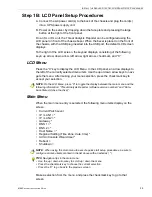
Page 9: ...rters USA Local 714 282 6111 Domestic US 1 888 786 7999 International 1 714 282 6111 M86 Security Taiwan Taipei Local 2397 0300 Domestic Taiwan 02 2397 0300 International 886 2 2397 0300 Procedures Wh...

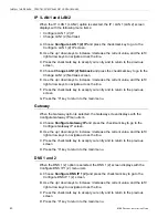
Page 10: ...taining supplemental product applications and EULA User guides can be obtained at http www m86security com support Threat Analysis Reporter documentation asp NOTES Threat Analysis Reporter servers com...

Page 11: ...urces of vibration or physical shock Isolated from strong electromagnetic fields and noise caused by electrical devices such as elevators copy machines air conditioners large fans large electric motor...

Page 12: ...nection of the server to the power supply will not overload any circuits Consideration should be given to the connection of the equipment to the supply circuit and the effect that overloading of the c...

Page 13: ...entify the Sections of the Rack Rails You should have received two rack rail assemblies with the M86 Security server unit Each of these assemblies consists of two sections An inner fixed chassis rail...

Page 14: ...snugly into the rack Secure the short bracket to the front side of the outer rail with two M4 screws and the long bracket to the rear side of the outer rail with three M4 screws Repeat these steps fo...

Page 15: ...unit The next step is to install the server chassis into the rack Do this by lining up the rear of the chassis rails with the front of the rack rails Slide the chassis rails into the rack rails keepin...

Page 16: ...First determine how far follow the server will extend out the front of the rack A larger chassis should be positioned to balance the weight between front and back If a bezel is included on your serve...

Page 17: ...t inner slide against the hooks on the right side of the chassis as show below on the left 3 Securely attach the slide to the chassis with two M4 flat head screws and repeat the steps 1 3 to install t...

Page 18: ...s to the Rack 1 After you have installed the short and long brackets to the outer slides you are ready to install the whole slide assemblies outer slides with short and long brackets attached to the r...

Page 19: ...IDE 13 Install the Chassis into the Rack 1 Push the inner slides which are attached to the chassis into the grooves of the outer slide assemblies that are installed in the rack as shown below 2 Push t...

Page 20: ...ll the chassis into the rack To avoid personal injury and property damage please carefully follow all the safety steps listed below Before installing the chassis rails Close the chassis using the chas...

Page 21: ...orre sponding holes on each of the inner rail 4 Attach an inner rail to each side of the chassis and secure the inner rail to the chassis by inserting three Type G screws through the holes on each sid...

Page 22: ...ar 2 Secure the front short bracket marked with the Up Front arrows to the outer rail with two Type G screws See the previous page for a description of the Type G screw 3 Attach the rear long bracket...

Page 23: ...ARY SETUP PROCEDURES RACK MOUNT THE SERVER M86 SECURITY INSTALLATION GUIDE 17 8 You will need to release the safety taps on both sides of the chassis in order to completely remove the chassis out of t...

Page 24: ...racks with the depth of 28 to 33 Determine the placement of each component in the rack before you install the rails Install the heaviest server components on the bottom of the rack first and then wor...

Page 25: ...the previous page for descriptions of Type H and Type I hardware components 4 Attach the rear long bracket to the rear end of the rack and secure it to the rack with two Type H screws and Type I wash...

Page 26: ...PRELIMINARY SETUP PROCEDURES RACK MOUNT THE SERVER 20 M86 SECURITY INSTALLATION GUIDE 6 Slide the inner rails which are attached to the chassis into the outer rails on the rack...

Page 27: ...m is adequately supported Make sure that all the components are securely fastened to the chassis to prevent components falling off from the chassis The rack assembly should be properly grounded to avo...

Page 28: ...uring shipping A Hold the bezel upright and facing towards you Fig 1 Fig 1 Front of bezel B Note that each end of the bezel contains two raised bumps Fig 2 C Align these bumps along the two parallel g...

Page 29: ...rican and Pacific Rim countries Power Supply Precautions WARNING Use a regulating uninterruptible power supply UPS to protect the server from power surges voltage spikes and to keep the server operati...

Page 30: ...N There are no user serviceable components inside the chassis The chassis should only be opened by qualified service personnel Never disassemble tamper with or attempt to repair the server Doing so ma...

Page 31: ...Electrical Safety Precautions WARNING Heed the following safety precautions to protect yourself from harm and the server from damage CAUTION Dangerous voltages associated with the 100 240 V AC power...

Page 32: ...There is a danger of explosion if the battery on the motherboard is installed upside down which will reverse its polarities CAUTION DANGER OF EXPLOSION IF BATTERY IS INCORRECTLY REPLACED REPLACE ONLY...

Page 33: ...Analysis Reporter with AC power cord s either one of two options PC monitor with AC power cord and keyboard or PC laptop computer with HyperTerminal and serial port cable and USB DB9 serial adapter if...

Page 34: ...n at the right of the front panel see Fig 3 for an SL unit Fig 4 for an MSA unit and Fig 5 for an HL unit Once the Threat Analysis Reporter is powered up proceed to the Quick Start menu instructions S...

Page 35: ...gram of SL chassis front panel power button at far right Fig 4 Diagram of MSA chassis front panel power button at far right Fig 5 Diagram of HL chassis front panel power button at far right Once the T...

Page 36: ...nd do not have an equivalent type of terminal emulator program installed on your workstation Hilgraeve Inc the maker of HyperTerminal offers HyperTerminal Private Edition for Windows Vista and Windows...

Page 37: ...d then click OK to open the Connect To dialog box C At the Connect using field select the COM port assigned to the serial port on the laptop probably COM1 and then click OK to open the Properties dial...

Page 38: ...rminal session window go to File Properties to open the Prop erties dialog box displaying the Connect To and Settings tabs G Click the Settings tab and at the Emulation menu select VT100 H Click OK to...

Page 39: ...screensaver currently displays on your screen press the Enter key to display the login screen A At the login prompt type in menu B Press the Enter key to display the Password prompt C At the Password...

Page 40: ...display the confirmation prompt C Press Y for Yes to confirm and save your entries for the LAN1 interface and to go to the next screen D At the Enter interface lan2 IP address field enter the IP addr...

Page 41: ...A At the Enter first DNS server IP field enter the IP address for the primary Domain Name Server Press Enter to go to the next screen B At the Enter optional second DNS server IP field if you have a s...

Page 42: ...onfirm and save your regional selec tion and to go to the next screen B Use the up and down arrows in your keyboard to select your region After selecting your locality press Y for Yes to confirm and s...

Page 43: ...n to the Administration menu NOTE When saving your entries there may be a 4 10 second delay before the Adminis tration menu displays Administration menu After making all entries using the Quick Start...

Page 44: ...tive Default gateway IP address specified in screen 5 Configure default gateway Configure host name specified in screen 7 Configure Host Name DNS server IP address es specified in screen 6 Configure D...

Page 45: ...e left of the currently selected menu item Use the up or down arrow keys to navi gate the menu After making your menu selection press the checkmark key to accept your selection NOTE On the LCD Menu pr...

Page 46: ...your entry and to return to the previous screen G Press the X key to return to the main menu Gateway When the Gateway option is selected the Gateway screen displays with the Configure Gateway IP menu...

Page 47: ...n menu Regional Setting Time Zone date time When the Regional Setting Time Zone date time option is selected the Regional Setting Time Zone date time screen displays with the Region menu item A Choose...

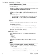
Page 48: ...creen displays with two menu items A Choose one of two options Yes shutdown now This selection shuts down the Threat Analysis Reporter No cancel shutdown This selection returns you to the previous scr...

Page 49: ...to the previous screen LCD Controls When the LCD Controls option is selected the LCD Controls screen displays with the following menu items Contrast On Brightness Off Brightness A Choose one of the m...

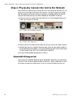
Page 50: ...at Analysis Reporter s LAN 1 port the port on the left Fig 1 Portion of SL and MSA chassis rear Fig 2 Portion of HL chassis rear B Plug the other end of the CAT 5E cable into an open port on the netwo...

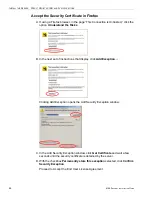
Page 51: ...nter https 10 10 10 10 8443 8e6tar in the browser s address field C Click Go to display the security issue page If using Firefox proceed to Accept the Security Certificate in Firefox If using IE proce...

Page 52: ...rstand the Risks B In the next set of instructions that display click Add Exception Clicking Add Exception opens the Add Security Exception window C In the Add Security Exception window click Get Cert...

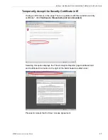
Page 53: ...using an IE browser in the page There is a problem with this website s security certificate click Continue to this website not recommended Selecting this option displays the Threat Analysis Reporter...

Page 54: ...w Safari can t verify the identity of the website opens Click Show Certificate to open the certificate information box at the bottom of this window B Click the Always trust checkbox and then click Con...

Page 55: ...the Threat Analysis Reporter Wizard A In the Username field of the Login window type in the username specified in the Configure Wizard user screen of the Quick Start Setup Procedures Step 1A or the Ad...

Page 56: ...al administrator who will be notified via email regarding system alerts C Enter the Password to be used with that username and enter the same pass word again in the Confirm Password field Enter Bandwi...

Page 57: ...by following steps A through D again The Source Web Filter is designated by an X in the Source column of the list box To specify a Source Web Filter server from available entries in the list box selec...

Page 58: ...for the Threat Analysis Reporter to ensure secure exchanges between the appliance and your browser A In the Threat Analysis Reporter login window type in the Username and Pass word registered for the...

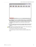
Page 59: ...fterwards this application server would restart Would you like to continue E Click Yes to begin the process Once the self signed certificate has been gener ated you will be logged out of the TAR user...

Page 60: ...sta with IE 7 or 8 Windows 7 with IE 8 Windows XP or Vista with IE 7 or 8 A If using an IE 7 or 8 browser on a Windows XP or Vista machine in the page There is a problem with this website s security c...

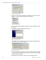
Page 61: ...tificate Invalid pop up box Figure B Windows XP IE 7 C Click View certificates to open the Certificate window that includes the host name you assigned to TAR Figure C Windows XP IE 7 D Click Install C...

Page 62: ...click OK to close the pop up box H Click Next to display the last page of the wizard Figure H Windows XP IE 7 I Click Finish to close the wizard and to open the Security Warning dialog box asking if...

Page 63: ...the Certificate Error button to the right of the field shaded a reddish color see Figure A2 Click Certificate Error to open the Certificate Invalid pop up box see Figure B Click View certificates to o...

Page 64: ...C WINDOWS system32 drivers etc in the Address field to open the folder where the hosts file is located B Double click hosts to open a window asking which program you wish to use to open the file Doub...

Page 65: ...LATION GUIDE 59 D In the address field of your newly opened IE browser from now on you will need to use TAR s host name instead of its IP address that is https host name 8443 8e6tar would be used inst...

Page 66: ...ning on your network the next step is to set up user groups or administrator groups You will set up and configure gauges thereafter Obtain the latest Threat Analysis Reporter User Guide from our Web s...

Page 67: ...instructions and tips on using tools in the console to fulfill the scenarios described above Threat Analysis Reporter Usage Scenarios This collection of setup and usage scenarios is designed to help y...

Page 68: ...anels used for viewing configuring URL bandwidth gauges and or gauge activity Dashboard view current gauge activity Overall Ranking view details about current gauge activity for all end users affectin...

Page 69: ...splay its menu Click any of the menu topics to display panels used for configuring profiles and maintaining the server Admin Trails view a list of alert records for the most recent time period Device...

Page 70: ...h URLs they are visiting Step A Select the gauge with the highest score 1 In the URL dashboard select the gauge with the highest score and click it to open the Gauge Ranking table showing columns with...

Page 71: ...anel is populated with rows of records for Threats affected by the selected end user Now that you ve identified the user affecting the highest scoring gauge next you will investigate the activity of t...

Page 72: ...reat select the Threat with the highest score and then click it to display a list of URLs the user visited in the right side of this panel 2 Choose a URL you wish to view and then click it to open a s...

Page 73: ...ge Ranking table by going to the lower left corner of the Threat View User panel and clicking the Back button In the User Name column click that user s link to display the User Summary panel for that...

Page 74: ...nd users are driving the score in one or more gauges and how to view URLs visited by the user When you become accustomed to using the Threat Analysis Reporter on a regular basis to conduct these types...

Page 75: ...tracking gauge activity 1 60 minutes For this exercise we will use the default and recommended value which is 15 minutes d Gauge Method to be used for tracking gauge activity For this exercise we will...

Page 76: ...t the user group to highlight it 6 Click add to move the user group to the Assigned User Groups list box 7 After adding users click Save at the bottom right of the panel to return to the Add Edit Gaug...

Page 77: ...real time with Internet usage issues that endanger your network and or consume an excessive amount of bandwidth resources IV Create an email alert exercise This exercise will teach you how to set up a...

Page 78: ...arget panel to the right containing the Email Addresses and Low Lockout Components accordions 4 Type in the Alert Name to be used for the alert that will be delivered to the group administrator 5 Spec...

Page 79: ...a gauge alert For this exercise however you will only want to select Email as described in the next step In the Threat Analysis Reporter User Guide index see How to add a new alert Step C Select Email...

Page 80: ...ess that was specified The email alert identifies the end user who triggered the alert and includes a list of URLs the user visited along with the date and time each URL was accessed Clicking any of t...

Page 81: ...he status of a feature on the unit while buttons let you perform a function on the unit LED Indicator Color Condition Description Power Green On System On Off System Off HDD Amber Blinking HDD Activit...

Page 82: ...ting condition which may be caused by cables obstructing the airflow in the system or the ambient room temperature being too warm NIC2 icon A flashing green LED indicates network activity on LAN2 NIC1...

Page 83: ...HL chassis to the left of the power supplies a steady blue UID LED indicator displays when the UID button on the control panel is pressed This LED remains lit until the UID button is pressed again Po...

Page 84: ...ont panel Below is a chart of LED indicators in the SL and HL unit LED Indicator Color Condition Description LOG Green On Downloading a log Off No log download detected RAID Green On RAID mode enabled...

Page 85: ...fety Compliance Electromagnetic Compatibility EMC USA UL 60950 1 2nd ed 2007 Europe Low Voltage Directive LVD 2006 95 EC to CB Scheme EN 60950 2006 International UL CB to IEC 60950 1 2006 USA FCC CFR...

Page 86: ...sonable protection against harmful interference when the equipment is operated in a commercial environment This equipment generates uses and can radiate radio frequency energy and if not installed and...

Page 87: ...CLARATION OF THE MANUFACTURER OR IMPORTER M86 SECURITY INSTALLATION GUIDE 81 Electromagnetic Compatibility Class A Notice Industry Canada Equipment Standard for Digital Equipment ICES 003 Bureau of St...

Page 88: ...REGULATORY SPECIFICATIONS AND DISCLAIMERS DECLARATION OF THE MANUFACTURER OR IMPORTER 82 M86 SECURITY INSTALLATION GUIDE EC Declaration of Conformity European Community Directives Requirement CE...

Page 89: ...accessories are included Save all packing materials in the event that the unit needs to be returned to M86 Security The NetOptics box should contain the following items 1 NetOptics 10 100BaseT Tap 2...

Page 90: ...m the unit to the power source AC power in rear panel of NetOptics 10 100BaseT Tap B If a designated source Web Filter to be used with the Threat Analysis Reporter is already installed on the network...

Page 91: ...ble connect one end to the Ethernet Tap s Network B port F Connect the other end of the straight through cable to the Web Filter s listening interface G Using the second straight through cable connect...

Page 92: ...APPENDIX OPTIONAL ETHERNET TAP INSTALLATION INSTALL THE ETHERNET TAP UNIT 86 M86 SECURITY INSTALLATION GUIDE...

Page 93: ...password 37 crossover cable 4 E EMC 79 F FCC 79 H HL 4 7 22 24 28 29 44 76 77 78 HyperTerminal Setup 30 I ICES 003 79 81 Install Bezel 22 Install Tap 83 L LCD Panel 27 39 Login screen 33 LVD 79 M MSA...

Page 94: ...SECURITY INSTALLATION GUIDE R Rack Setup Precautions 6 RAID 78 reboot 42 RoHS compliant 82 S serial port cable 27 28 shut down 63 SL 11 22 28 29 44 75 78 spare parts kit 4 U UID 76 77 UL 79 W Web Filt...

Page 95: ......

Page 96: ...M86 Security Corporate Headquarters USA 828 West Taft Avenue Orange CA 92865 4232 Tel 714 282 6111 or 888 786 7999 Fax 714 282 6116 Sales Technical Support 714 282 6117 General Office...

Reviews: