VAN DER GRAAF
VERY LOW NOISE POWER SUPPLY
REVISION P
R
A – JUNE 2014
Copyright © 2014, M2Tech Srl
18
M2Tech
www.m2tech.biz
6. Outputs Toggle
When the
VAN DER GRAAF
is in standby (only LED 4 on), it is possible to activate it
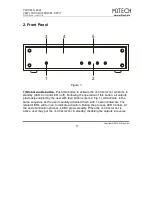
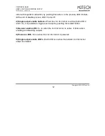
pushing the global enable button (Fig. 1, 1). Immediately after this button operation,
the global enable LED (Fig. 1, 3) starts blinking and the previously enabled outputs
are activated in the order chosen by the user, at one second intervals. At the end of
the activation process, the active outputs are indicated by the related LED, which is
on, and the global enable LED glows steadily.
When
VAN DER GRAAF
is active, it can be put in standby pushing the global enable
button once more. Following this action, the global enable LED starts blinking and the
active outputs are shut down in the reverse order with respect to the activation order.
For example: if the activation sequence is: OUT3-OUT1-OUT2, the outputs will be
shut down in the following order: OUT2-OUT1-OUT3. At the end of the process, the
enable indication LED’s of all outputs are off and the global enable LED stops
blinking and remains off.
NOTE: the outputs activation sequence is stored by the
VAN DER GRAAF
VAN DER GRAAF
VAN DER GRAAF
VAN DER GRAAF
when it
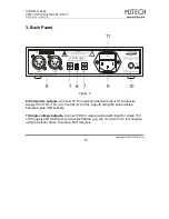
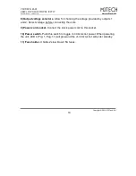
enters standby. If the power switch (Fig. 2, 10) is used to shut down the
VAN DER
VAN DER
VAN DER
VAN DER
GRAAF
GRAAF
GRAAF
GRAAF
, then the sequence, even if changed from the previous standby, is not
stored and the
VAN DER GRAAF
VAN DER GRAAF
VAN DER GRAAF
VAN DER GRAAF
will use the last stored sequence upon following
activation, not the latest one.
The ability to activate the outputs in a chosen order is very useful whenever the units
in the chain powered by the
VAN DER GRAAF
need to be turned on in a given order.

