


Tools: Phillips head screw driver, ‘green’, 11/32” nutdriver, 7/16” wrench, 7/16” socket, socket wrench,
tape measure, and a friend.
NOTE: To prevent galling of the stainless steel hardware, apply a light coating of Penetrox to all bolts
and screws. The term ‘SWAGE’ refers to a physical reduction made in one diameter of tubing in order to
fit into or over another.
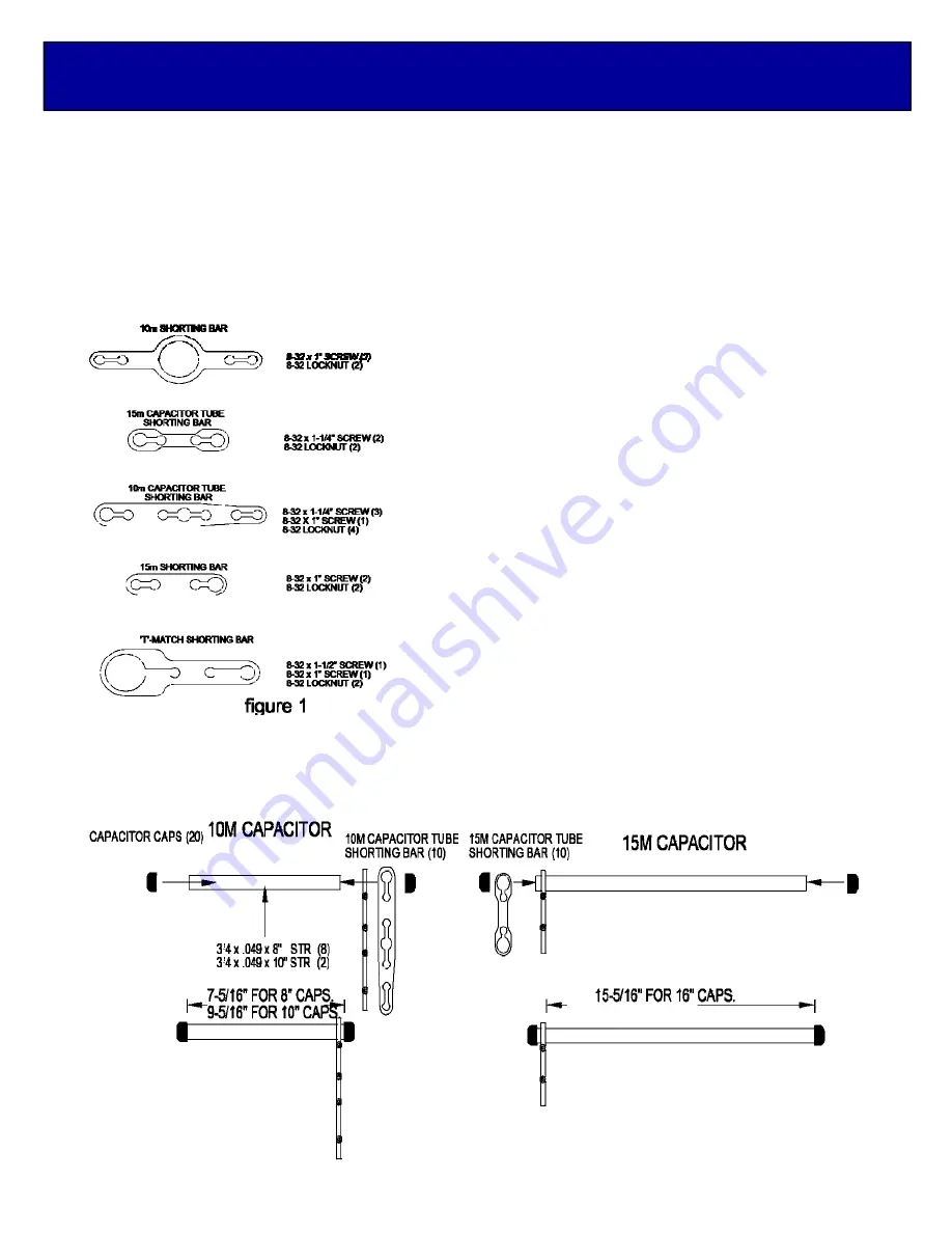
1. SHORTING BARS
Included with this kit are five different shorting bars, pictured in Figure 1. First locate the 10m shorting bars and
shorting bar insulators (black or white). For each 10m shorting bar press a single shorting bar insulator into the
large hole. This can be done initially with a vise or with a hammer and a block of wood. After the insulator has
been partially set into the hole,
take two element clamp plates and center the shorting bar on top
of the two plates. Now place the block of wood on top of the
insulator and give a final strike. You should hear a snap. This is
the indication that the insulator has been secured. Locate the
small container of Penetrox and for each shorting bar, apply a light
coating to the walls as indicated in the figure. Next install the 8-32
hardware listed to the right of each part into each respective
shorting bar. Remember to apply a light coating of Penetrox to the
threads of each screw. Finger tighten each locknut for now.
2. CAPACITOR TUBE ASSEMBLY
There are three sizes of capacitor tubes. Tube sizes 8” and 10”
are for the 10m capacitor while the 16” pieces are for 15m. Locate
the shorter 3/4” diameter tubes and arrange them according to
length. Also locate the bag of capacitor caps. As shown in Figure
2, starting with the 8” tube, lay a capacitor cap on a flat surface
and with your own strength press one of the tube ends into the
cap. Now slide on the shorting bar all the way to the cap, turn the
tube over, and install another cap. Each capacitor cap will engage
the 3/4” tube 3/8”(.375) so a measurement can be taken to insure
complete engagement of the caps to the tube, simply measure
between the inside edge of the two installed caps, it should be
5/8”(.625 to 3/4”(.750) shorter than the capacitor tube being
measured. Repeat this procedure for the 10” capacitor tube. For the 16” tubes follow the same procedure but
slide on a different shorting bar as shown in the figure.
KT36XA ASSEMBLY MANUAL
Summary of Contents for KT36XA
Page 8: ...KT36XA HALF ELEMEN GENERAL ASSEMBLY...
Page 9: ...KT36XA ASSEMBLY MANUAL...
Page 10: ...REAR DRIVEN ELEMENT DIMENSIONS...
Page 11: ...FRONT DRIVEN ELEMENT DIMENSIONS...
Page 12: ...1ST DIRECTOR ELEMENT DIMENSION...
Page 13: ...2ND DIRECTOR ELEMENT DIMENSION...
Page 14: ...3RD DIRECTOR ELEMENT DIMENSIONS...
Page 15: ...DUAL DRIVEN AND T MATCH ASSEMBLIES...
Page 16: ...KT36XA DIMENSION SHEET...


