


5
73VR31BLD USERS MANUAL EM-7397-C Rev.4
n
INSTALL
1. Select Add/Remove Programs under Control Panel (proceed through Start > Settings > Control Panel). Or double-
click My Computer icon on the desktop and click Control Panel to access Add/Remove Programs.
2. Double-click Add/Remove Programs to start.
3. Then the SETUP.exe will be executed and the installation will start.
4. After that, follow the step-by-step instructions that will appear on dialog boxes.
5. When the installation is successfully completed, “73VR31BLD” will be added to the menu under Programs.
n
REMOVE
1. To remove the 73VR31BLD, use Add/Remove Programs in Control Panel (proceed through Start > Settings >
Control Panel).
2. At the Add/Remove Programs dialog box, select the 73VR31BLD, and then the Flash window will appear, and
click Enter. Next, InstallShield Wizard will appear.
At the InstallShield Wizard, select Remove (check the radio button next to Remove) to accomplish the removing.
Note for Windows Vista or Windows 7.
1: If the ‘Install or run program’ appears in AutoPlay dialog box, allow 73VRPAC2.EXE.
2: If during installation ‘An unidentified program wants access to your computer’ appears in User Account Control
dialog box, then allow SETUP.EXE.
1.4 ACCESSING THE 73VR3100 DATA
1.4.1 ETHERNET
A PC with the 73VR31BLD installed and the 73VR3100 can communicate through Ethernet. The 73VR3100 must
be setup with an IP address in advance. Please refer to the 73VR3100 Users Manual to set the IP address.
n
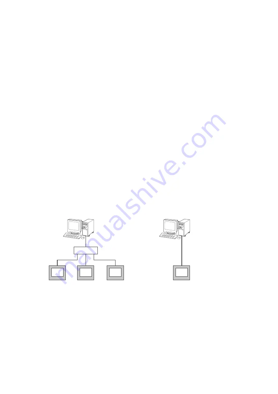
ETHERNET CABLE TYPE
When connecting the PC and the 73VR3100 via a switching hub, use Straight type cables.
When the 73VR3100 is directly connected to the PC, use a Reverse (interlink) type cable.
We recommend that you will choose connection with straight cables because the reverse cable connection may be
unstable.
n
CONFIRMING CONNECTION
If a Connect Error (Socket connector error!) is displayed during connecting procedure, you can use the PING com-
mand to check whether a connection is properly established with an input module.
Type the PING command at the MS-DOS prompt window, and in response to the command...
C:\WINDOWS > ping ***.***.***.***
(For ***.***.***.***, enter the IP address in decimal format.)
ping ***.***.***.*** with 32 bytes of data:
Reply from ***.***.***.***:bytes = 32 time < 10ms TTL = 64
Reply from ***.***.***.***:bytes = 32 time < 10ms TTL = 64
Reply from ***.***.***.***:bytes = 32 time < 10ms TTL = 64
Reply from ***.***.***.***:bytes = 32 time < 10ms TTL = 64
Ping statistics for ***.***.***.***
Packets:Sent = 4, Received = 4, Lost = 0(0% loss)
...in response to the PING command, if a proper connection is established, the above response is returned. If a con-
nection error takes place due to a wrong IP address you’ve typed, a ‘time expired’ notification will be shown.
Ethernet Cable (straight)
Ethernet Cable (straight)
PC Configurator
(model: 73VR31BLD)
Ethernet Cable
(reverse or interlink)
PC Configurator
(model: 73VR31BLD)
Switch / Hub
73VR3100
73VR3100
73VR3100
73VR3100