ADJUSTMENT PROCEDURE
This unit is calibrated at the factory to meet the ordered
specifications, therefore you usually do not need any cali-
bration.
For matching the signal to a receiving instrument or in case
of regular calibration, adjust the output as explained below.
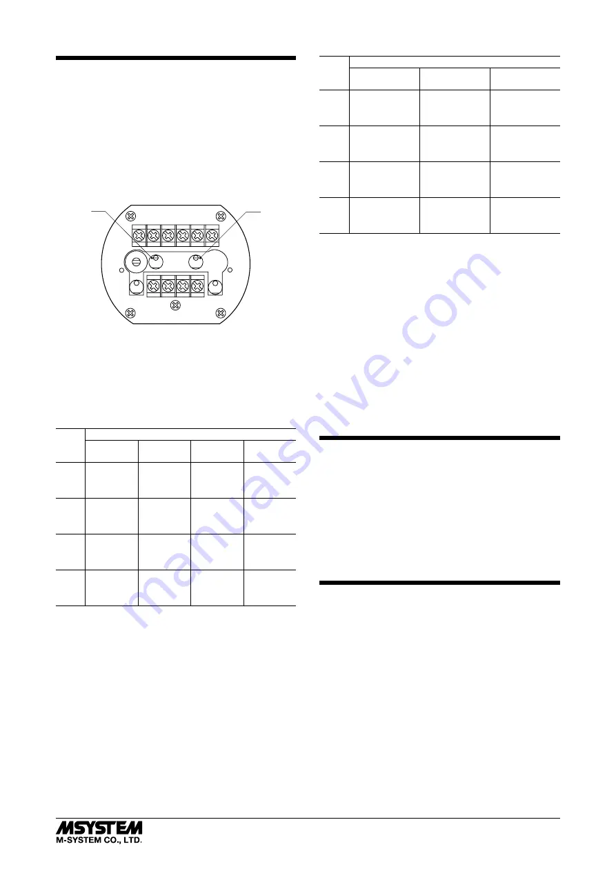
Zero and Span adjustments are located behind the top cover
of the unit. Open the enclosure cover, release the knurled
knobs at the front of the unit and open the top cover.
After the calibration is complete, be sure to close both cov-
ers.
1
2
3
4
5
6
SW1
VR22
VR1
VR2
VR21
SW1 : Frequency Selector
VR1 : Zero Adjustment
VR2 : Span Adjustment (fine)
VR21 : Bias Adjustment
VR22 : Span Adjustment (coarse)
■
INPUT FREQUENCY RANGE SETTING
Use SW1 for the frequency range setting.
SW1
FREQUENCY RANGE (Hz)
*
36 ≤
< 100
100 ≤
< 240
240 ≤
< 480
480 ≤
< 1000
1
34 – 38
85 – 95
170 – 190
340 – 380
2
38 – 43
95 – 105
190 – 220
380 – 430
3
43 – 48
105 – 120
220 – 240
430 – 480
4
48 – 54
120 – 135
240 – 270
480 – 540
5
54 – 60
135 – 150
270 – 300
540 – 600
6
60 – 66
150 – 165
300 – 330
600 – 660
7
66 – 74
165 – 185
330 – 370
660 – 740
8
74 – 82
185 – 205
370 – 410
740 – 820
9
82 – 92
205 – 230
410 – 460
820 – 920
10
92 – 102
230 – 255
460 – 510
920 – 1020
11
102 – 114
255 – 285
510 – 570
1020 – 1140
12
114 – 130
285 – 325
570 – 650
1140 – 1300
SW1
FREQUENCY RANGE (kHz)
*
1 ≤
< 2.4
2.4 ≤
< 4.8
4.8 ≤
< 12
1
0.85 – 0.95
1.7 – 1.9
3.4 – 3.8
2
0.95 – 1.05
1.9 – 2.2
3.8 – 4.4
3
1.05 – 1.20
2.2 – 2.4
4.4 – 4.8
4
1.20 – 1.35
2.4 – 2.7
4.8 – 5.4
5
1.35 – 1.50
2.7 – 3.0
5.4 – 6.0
6
1.50 – 1.65
3.0 – 3.3
6.0 – 6.6
7
1.65 – 1.85
3.3 – 3.7
6.6 – 7.4
8
1.85 – 2.05
3.7 – 4.1
7.4 – 8.2
9
2.05 – 2.30
4.1 – 4.6
8.2 – 9.2
10
2.30 – 2.55
4.6 – 5.1
9.2 – 10.2
11
2.55 – 2.85
5.1 – 5.7
10.2 – 11.4
12
2.85 – 3.25
5.7 – 6.5
11.4 – 13.0
* The frequency range can only be changed within the adjust-
ment range of the frequency variable range covering the
input range that you specified.
Example: If you specified the input range of 0 – 150 Hz
The range can be changed within 85 – 325 Hz.
■
OUTPUT ZERO & SPAN ADJUSTMENT
1) Turn the bias adjustment (VR21) fully counterclockwise.
2) ZERO: With 0% input frequency, adjust output to 0
±0.05% with VR1.
3) SPAN: With 100% input frequency, adjust output to 100
±0.05% with VR22 after turning VR2 fully counterclock-
wise and then 1.5 turns clockwise.
4) Check ZERO adjustment again with 0% input frequency.
5) When ZERO value is changed, repeat the above proce-
dure 2) – 4).
MAINTENANCE
Regular calibration procedure is explained below:
■
CALIBRATION
Warm up the unit for at least 10 minutes. Apply 0%, 25%,
50%, 75% and 100% input signal. Check that the output
signal for the respective input signal remains within accu-
racy described in the data sheet. When the output is out of
tolerance, recalibrate the unit according to the “ADJUST-
MENT PROCEDURE” explained earlier.
LIGHTNING SURGE PROTECTION
M-System offers a series of lightning surge protectors for
protection against induced lightning surges. Please contact
M-System to choose appropriate models.
6BPA
5-2-55, Minamitsumori, Nishinari-ku, Osaka 557-0063 JAPAN
Phone: +81(6)6659-8201 Fax: +81(6)6659-8510 E-mail: [email protected]
EM-8888 Rev.1 P. 5 / 5