background image

GB

ENGLISH  |    VISTUS-AD  

15

ASSEMBLY OF THE OUTDOOR STATION

The door intercom point is designed for surface mounting.

Preparation

When removing the front cover ensure that the nameplate does not fall 
out and become damaged.
Also take care of the cable in the loudspeaker, which is attached in the 
front part of the casing.

1.  Remove the two screws in order to be able to open the casing 

on the outdoor station. The casing is also fitted with notches and 
projections that connect the upper and lower parts of the casing. 
Thus a certain amount of force is necessary in order to separate the 
casing parts.

2.  Position the drilling template for the outdoor station in a level 

location at the intended assembly location (a spirit level is helpful 
for this) and attach it with sticky tape.

3.  Use the drilling template to drill the attachment holes with a 6mm 

drill and insert a dowel into each hole.

4.  Now remove the drilling template.
5.  Feed the lines through the large hole in the outdoor station and 

secure them with 4 screws.

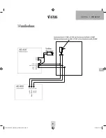
6.  Connect the line in accordance with the wiring plan.

Adjusting the nameplate

The nameplate comprises two transparent plastic parts that are
connected with 2 or 4 small screws.

7.  Remove all screws from the nameplate and take the plate apart. 

The foil for the name can be found between the plastic parts.

8.  Write on the foil with a smudge proof felt tip pen or print a 

nameplate* using a PC and printer.

9.  Lay the complete nameplate (foil) between the two plastic parts 

and screw them back together.

* Size of the nameplate:
VISTUS AD-4010: 71 mm x 50 mm
VISTUS AD-4020: 71 mm x 25 mm
VISTUS AD-4030: 71 mm x 15mm

10. Replace the nameplate in the front cover before re-attaching 

the front cover to the outdoor station. You can attach a strip of 
sticky tape over the nameplate and the casing to ensure that the 
nameplate does not fall out during assembly.

Note

: Remove the sticky tape from the casing immediately following 

installation in order to prevent damage to the front cover!

11.  Screw the front cover on using both casing screws. Please ensure 

that the screws are not tilted as this can damage the thread in the 
lower section of the casing.

ASSEMBLY OF THE INDOOR STATION

The installation height of the Indoor stations can be selected freely 
according to your circumstances.
1.  The casing on the indoor station is kept together with notches and 

projections. To separate the lower section from the front section, 
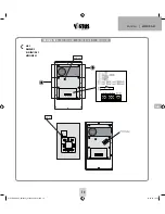
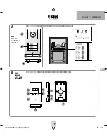
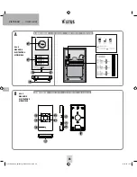
press a small slotted screwdriver against the snap fastener (B.15) 
on the bottom side. 

2.  Use the lower section of the casing as an aid to mark the drill 

holes. Make sure that you hold the lower section in a horizontal 
position for this step.

NOTE

: The lower casing section on the indoor station can also be 

attached to a hollow wall box. The corresponding attachment holes 
are located around the line feed hole. If this does not provide 
enough hold then drill more holes and use them to also screw the 
indoor station in place.

3.  Drill the attachment holes with a 6 mm drill and insert one dowel 

in each hole.

4.  Feed the lines through the feed hole in the lower casing part 

designed for this purpose and screw this down.

5.  Attach the lines in accordance with the wiring plan and replace the 

front casing section onto the lower casing section. Make sure that 
it clicks correctly into place.

CONNECTION

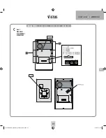
An exact description of where the individual connections and terminals 
are located can be found in the figures. The recommended wiring can 
be seen in the corresponding wiring plan in the affix.

Connect the lines to the audio, +15V and GND on the outdoor station. 
These terminals are also present on the indoor stations and need to be 
connected to one another 1:1.

Note on the 2-family version

: One four-pole connection terminal 

is present in each residential unit. The connection terminals are numbe-
red. Connection terminal 1 is for the lower and connection terminal 
2 is for the upper bell button.

Note on the 3-family version

: One four-pole connection terminal 

is present in each residential unit. The connection terminals are numbe-
red. Connection terminal 1 is for the lower, connection terminal 2 is for 
the middle and connection terminal 3 is for the upper bell button.

VISTUS AD-400_I-Manual_210x240_Fin13.indd   15

01.03.16   15:19

Summary of Contents for VISTUS AD-4010

Page 1: ...VISTUS AD 400 VISTUS AD 410 VISTUS AD 420 VISTUS AD 430 VISTUS AD ALU 410 VISTUS AD ALU 420 VISTUS AD ALU 430 BETRIEBSANLEITUNG OPERATING INSTRUCTIONS MODE D EMPLOI GEBRUIKSAANWIJZING VISTUS AD 400_I...

Page 2: ...TRATION B AFBEELDING B A B VISTUS AD DEUTSCH DE 2 2 3 7 6 3 4 5 13 12 11 14 15 AUSSENSTATION OUTDOOR STATION BO TIER EXT RIEUR BUITENSTATION INNENSTATION INDOOR STATION BO TIER INT RIEUR BINNENSTATION...

Page 3: ...C DIAGRAM C ILLUSTRATION C AFBEELDING C C DEUTSCH VISTUS AD 3 INNENSTATION INDOOR STATION BO TIER INT RIEUR BINNENSTATION Bell Volume VTX Bell 1 1 VISTUS AD 400_I Manual_210x240_Fin13 indd 3 01 03 16...

Page 4: ...t werden oder 2 sternf rmig parallel von einem zentralen Punkt Verteilerkasten aus Der Verdrahtungsplan im Anhang basiert auf einer stern f rmigen Verdrahtung da diese zu bevorzugen ist Die Leitungen...

Page 5: ...vorhanden und m ssen nur 1 1 miteinander verbunden werden MONTAGE DER AU ENSTATION Die T rsprechstelle ist f r eine Aufputz Montage vorgesehen Vorbereitung Achten Sie beim Abnehmen des Frontcovers dar...

Page 6: ...ilien Versionen ist zu beachten dass die richtige Audio Leitung genutzt wird Audio1 und GND f r Familie 1 Audio2 und GND f r Familie 2 sowie Audio3 und GND f r Familie 3 Hinweis Ist ein Etagentaster a...

Page 7: ...geschaltet z B an Toreinfahrt und Haus wird ber die DIP Schalter Abb A ID CODE der ID Code eingestellt ID1 Schalter 1 on Schalter 2 on ID2 Schalter 1 on Schalter 2 off ID3 Schalter 1 off Schalter 2 on...

Page 8: ...tung ist eine Publikation der m e GmbH modern electronics An den Kolonaten 37 D 26160 Bad Zwischenahn Diese Bedienungsanleitung entspricht dem technischen Stand bei Drucklegung nderung in Technik und...

Page 9: ...DE DEUTSCH VISTUS AD 9 1 Familienhaus VISTUS AD 400_I Manual_210x240_Fin13 indd 9 01 03 16 15 19...

Page 10: ...VISTUS AD DEUTSCH DE 10 2 Familienhaus VISTUS AD 400_I Manual_210x240_Fin13 indd 10 01 03 16 15 19...

Page 11: ...DE DEUTSCH VISTUS AD 11 3 Familienhaus VISTUS AD 400_I Manual_210x240_Fin13 indd 11 01 03 16 15 19...

Page 12: ...bb B DIAGRAM B ILLUSTRATION B AFBEELDING B A B 2 3 7 6 3 4 5 13 12 11 14 15 AUSSENSTATION OUTDOOR STATION BO TIER EXT RIEUR BUITENSTATION INNENSTATION INDOOR STATION BO TIER INT RIEUR BINNENSTATION 6...

Page 13: ...H VISTUS AD 13 Abb C DIAGRAM C ILLUSTRATION C AFBEELDING C C INNENSTATION INDOOR STATION BO TIER INT RIEUR BINNENSTATION Bell Volume VTX Bell 1 1 GB VISTUS AD 400_I Manual_210x240_Fin13 indd 13 01 03...

Page 14: ...1x Assembly materials Scope of delivery VISTUS AD 410 AD ALU 410 1x Outdoor station with one bell button 1x Assembly materials Scope of delivery VISTUS AD 420 AD ALU 420 1x Outdoor station with two be...

Page 15: ...th casing screws Please ensure that the screws are not tilted as this can damage the thread in the lower section of the casing ASSEMBLY OF THE INDOOR STATION The installation height of the Indoor stat...

Page 16: ...played when the floor button is activated This ring tone is fixed and is not included in the normal tones melodies to make it easy to differentiate Connecting the wireless expansion model VTX BELL Th...

Page 17: ...eaking volume The two side buttons B 12 and 13 can be used to set the speaking volume in several steps Button 12 is used to increase the volume and button 13 to reduce it Melody selection The next mel...

Page 18: ...g a vacuum cleaner Do not hold the vacuum cleaner nozzle directly against the unit SAFETY INSTRUCTION In the event of damage to the housing connectors power cables or isolation shielding switch off th...

Page 19: ...A Abb B DIAGRAM B ILLUSTRATION B AFBEELDING B A B 2 3 7 6 3 4 5 13 12 11 14 15 AUSSENSTATION OUTDOOR STATION BO TIER EXT RIEUR BUITENSTATION INNENSTATION INDOOR STATION BO TIER INT RIEUR BINNENSTATION...

Page 20: ...S AD FRAN AIS 20 Abb C DIAGRAM C ILLUSTRATION C AFBEELDING C C INNENSTATION INDOOR STATION BO TIER INT RIEUR BINNENSTATION Bell Volume VTX Bell 1 1 VISTUS AD 400_I Manual_210x240_Fin13 indd 20 01 03 1...

Page 21: ...allation Mat riel fourni avec VISTUS AD 400 1 x bo tier int rieur 1 x kit d installation Mat riel fourni avec VISTUS AD 410 AD ALU 410 1 x bo tier ext rieur avec bouton de sonnette 1 x kit d installat...

Page 22: ...in d viter qu elles ne tombent lors du montage Remarque Enlevez le morceau de ruban adh sif du bo tier d s que l installation est termin e afin de ne pas d endommager le couvercle 11 Vissez le couverc...

Page 23: ...bitation Il y a une borne 6 p les par b timent d habitation Les bornes sont num rot es La borne 1 correspond au bouton de la sonnette du bas la borne 2 celui de la sonnette du milieu et la borne 3 cel...

Page 24: ...Dur e d ouverture du syst me d ouverture de la porte Le commutateur DIP illustration A Door opener time permet de r gler la dur e d ouverture du syst me d ouverture de la porte Il est possible de cho...

Page 25: ...as d alarme Cette notice est une publication de la soci t m e GmbH modern electronics An den Kolonaten 37 26160 Bad Zwischenahn Allemagne Cette notice est conforme la r glementation en vigueur lors de...

Page 26: ...A Abb B DIAGRAM B ILLUSTRATION B AFBEELDING B A B 2 3 7 6 3 4 5 13 12 11 14 15 AUSSENSTATION OUTDOOR STATION BO TIER EXT RIEUR BUITENSTATION INNENSTATION INDOOR STATION BO TIER INT RIEUR BINNENSTATIO...

Page 27: ...ANDS VISTUS AD 27 Abb C DIAGRAM C ILLUSTRATION C AFBEELDING C C INNENSTATION INDOOR STATION BO TIER INT RIEUR BINNENSTATION Bell Volume VTX Bell 1 1 VISTUS AD 400_I Manual_210x240_Fin13 indd 27 01 03...

Page 28: ...erbinding kan 1 serieel van binnenstation naar binnenstation uitgevoerd worden of 2 stervormig parallel vanuit een centraal punt verdeeldoos Het meegeleverde bedradingsschema is gebaseerd op een sterv...

Page 29: ...rug te plaatsen Opdat de naambordjes bij de montage niet uit de frontcover vallen kunt u aan de voorkant een stuk plakband over de naambordjes en de frontcover plakken Opmerking Om beschadiging van de...

Page 30: ...klok mee tot de aanslag en dan een klein beetje terug Door de potentiometer tegen de wijzers van de klok in te draaien wordt de geluidssterkte verminderd Opmerking m b t tot de tweegezinswoning versi...

Page 31: ...an het huis dan kan de ID code met de DIP schakelaar afb A ID CODE worden ingesteld ID 1 schakelaar 1 on en schakelaar 2 on ID 2 schakelaar 1 on en schakelaar 2 off ID 3 schakelaar 1 off en schakelaar...

Page 32: ...alarm Deze gebruiksaanwijzing is een publicatie van m e GmbH modern electronics An den Kolonaten 37 26160 Bad Zwischenahn Duitsland Deze gebruiksaanwijzing voldoet aan de technische eisen bij het ter...

Page 33: ...VISTUS AD 33 33 1 family house VISTUS AD 400_I Manual_210x240_Fin13 indd 33 01 03 16 15 19...

Page 34: ...VISTUS AD 34 34 2 family house VISTUS AD 400_I Manual_210x240_Fin13 indd 34 01 03 16 15 19...

Page 35: ...VISTUS AD 35 35 3 family house VISTUS AD 400_I Manual_210x240_Fin13 indd 35 01 03 16 15 19...

Page 36: ...ng mit den grundlegenden Anforderungen und den brigen einschl gigen Bestimmungen be ndet KONFORMIT TSERKL RUNG kann unter folgender Adresse gefunden werden http www m e de download ce vistus ad 4000ce...

Reviews: