M-Audio Trigger Finger User Manual Download Page 8

10


Enigma Software

The Enigma Editing software makes creating, editing, and storing memory setups for the Trigger Finger a snap. Its simple, drag-and-drop interface streamlines the 
re-programming process, and it also gives access to a few extra features. Additionally, memory setups can be stored on the computer, thus allowing you to amass 
a collection of more than 16 memory setups.

Installing Enigma

Enigma is located on the supplied MIDI Controller CD-ROM. This is the most current version at the time of pressing. We still recommend, however, that you check the 
M-Audio website (www.m-audio.com) for the latest version of the program as there may have been updates since the CD-ROM was originally made.

Windows Users:

1.  Run the file ‘enigma_pc.exe’.
2.  Follow the onscreen instructions.

Mac OS X Users:

1.  Double-click on the file ‘enigma_mac.dmg’.
2.   Drag ‘Enigma’ to the location on your hard drive where you want to install the software (we recommend placing Enigma in your Applications folder). 

Navigating Enigma

As long as the Trigger Finger is connected to your computer and correctly installed, Enigma will recognize your Trigger Finger on start up. You will see the Trigger 
Finger listed in the bank list (the window in the top left hand corner) with a red symbol next to it. If this is not the case, please consult the troubleshooting section.

The Device List

Enigma is an editor and librarian that has been developed to support the entire range of programmable products from M-Audio. As a result, you will see a number 
of other M-Audio and Evolution controllers listed in the bank window. These are provided to let you swap presets between different controllers. For example, if you 
wanted to set up a control for Reason’s Subtractor synth, you could copy the controls directly from the UC-33e’s Reason Subtractor preset to the controls of your 
Trigger Finger.

As well as the red device (your connected Trigger Finger controller), other devices in the device list are represented with blue symbols (blue devices) and orange 
symbols (orange devices). Blue devices represent the factory presets of the various controllers. If you send the blue ‘Trigger Finger defaults’ file to your Trigger Finger, 
it has the effect of performing a factory reset. Orange devices are your own user-created devices. You can create as many of these as you like simply by clicking on 
the ‘+’ button in the bottom left hand corner.

The Preset List

The Preset List is positioned directly underneath the device window. Click on the red device in the list. This device represents the physical memory on your Trigger 
Finger unit. You will see that all the presets of the Trigger Finger are listed with their factory default names. Note that although you can name presets anything you 
like, the Trigger Finger itself does not store these names. The naming of presets is an Enigma function only. If you click on other devices in the device list, you will 
see that the preset list updates accordingly.

Data Display

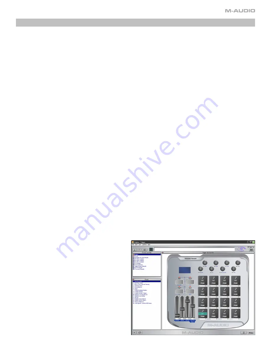
The main area in the Enigma software is reserved for displaying the data contained in the preset you have currently selected in the Preset List. Normally, you will see 
a graphical representation of the controller that is selected in the Device List. The View Select button in the bottom right-hand corner enables you to switch between 
the Graphic View and a more detailed List View. The List View is useful as a quick reference for the entire contents of the preset.

Click on the red device in the device list to select the Trigger Finger. Click on the View Select button to select the Graphic view. You will now see your Trigger Finger 
represented in Enigma. Now double-click on one of the controllers. This brings up the ‘Editor’ dialog. In the editor dialog you are able to change the assigned 
parameters for the controller you have selected.

Communication Between the Trigger Finger and Enigma

Enigma  communicates  with  your  Trigger  Finger  controller  using  the  three 
buttons above the Device List. If you move the mouse over each of these 
three buttons, you will see a tool tip which describes the function of each 
button. From left to right, the buttons are:

•   Receive:

 This button will update the red device in the Device List with 

the current contents of your Trigger Finger’s memory. Note that it is 
always the red device that is updated, regardless of the bank you 
have selected currently.

•   Update:

 This button sends only the edits in the red device to your 

Trigger Finger controller. As such, it is a quicker data transfer.


•   Send:

  This  button  will  send  the  currently  selected  bank  to  your 

Trigger Finger device. 

Summary of Contents for Trigger Finger

Page 1: ...troller data and velocity data simultaneously Locked and Full Velocity Modes Selectable velocity curves Programmable with the Enigma Editing software included Memory presets for Reason Redrum Live Imp...

Page 2: ...er if you use multiple applications at once including applications that are ReWired together such as using Ableton Live as a host application and simultaneously running Propellerhead Reason as a slave...

Page 3: ...talled the Trigger Finger will appear in the computer as a simple MIDI device with one input port and one output port You will select the Trigger Finger input port as the MIDI input device in your aud...

Page 4: ...two velocity control modes Locked Velocity and Full Velocity When editing the Trigger Finger this button is used to select one of the 8 knobs for programming 8 Ctrl Note Mute Peek Button Pressing this...

Page 5: ...ill transmit its assigned MIDI note with the assigned On Velocity Lock value and assigned Off velocity value The Velocity On Lock value can be set individually for each pad in Edit Mode The Off value...

Page 6: ...channel used when the knob or slider transmits its data Range 0 to 16 0 Global MIDI Channel The process of programming the Trigger Finger s controls entails selecting a control to edit a pad knob or...

Page 7: ...a C chromatic scale changing this value to 2 will result in a D chromatic scale being sent when the pads are played Note that when the slider is positioned in the center the transpose value is 0 Globa...

Page 8: ...the effect of performing a factory reset Orange devices are your own user created devices You can create as many of these as you like simply by clicking on the button in the bottom left hand corner Th...

Page 9: ...from the pads The two valid CC assignments are explained below CC 147 Note On Off This CC setting results in the default behavior for the pads Pressing the pad will send a Note On message with the pl...

Page 10: ...Memory Presets Because of its extremely exible architecture there are many applications and uses for the Trigger Finger more than can be listed here However you will nd a few useful operation suggest...

Page 11: ...e features than you would if you just used Edit Mode on the unit itself One trick that will be available to you is the ability to assign no MIDI note to a pad just leaving its pressure control active...

Page 12: ...ey may save you from having to contact Technical Support Problem My Trigger Finger is not turning on Reason The Trigger Finger is not receiving power Solution If you are trying to power the Trigger Fi...

Page 13: ...872 0444 Technical Support Mac 1 800 638 2120 Technical Support fax 418 872 0034 Sales e mail infocanada m audio com Sales phone 866 872 0444 Sales fax 514 396 7102 Internet Home Page http www m audio...

Page 14: ...27 16 0 127 0 11 Hi Hat Closed F 1 127 OFF 0 127 24 0 127 0 12 Hi Hat Open A 1 127 OFF 0 127 25 0 127 0 13 Crash 1 C 2 127 OFF 0 127 32 0 127 0 14 Crash 2 A 2 127 OFF 0 127 40 0 127 0 15 Ride D 2 127...

Page 15: ...0 127 16 0 127 0 11 Hi Wood Block E 4 127 OFF 0 127 24 0 127 0 12 Low Wood Block F 4 127 OFF 0 127 25 0 127 0 13 Open Cuica G 4 127 OFF 0 127 32 0 127 0 14 Muted Cuica F 4 127 OFF 0 127 40 0 127 0 15...

Page 16: ...0 11 Bass drum C 1 87 OFF 0 127 24 0 127 0 12 Bass drum C 1 95 OFF 0 127 25 0 127 0 13 Bass drum C 1 103 OFF 0 127 32 0 127 0 14 Bass drum C 1 111 OFF 0 127 40 0 127 0 15 Bass drum C 1 119 OFF 0 127 4...

Page 17: ...0 127 16 0 127 0 11 Hi Hat A 1 127 OFF 0 127 24 0 127 0 12 Ride D 2 127 OFF 0 127 25 0 127 0 13 Bass Drum C 1 127 OFF 0 127 32 0 127 0 14 Snare D 1 127 OFF 0 127 40 0 127 0 15 Hi Hat Open F 1 127 OFF...

Page 18: ...10 Hi Hat F 1 88 OFF 0 127 16 0 127 0 11 Hi Hat F 1 100 OFF 0 127 24 0 127 0 12 Hi Hat F 1 127 OFF 0 127 25 0 127 0 13 Crash C 2 64 OFF 0 127 32 0 127 0 14 Crash C 2 88 OFF 0 127 40 0 127 0 15 Crash...

Page 19: ...OFF 0 127 16 0 127 0 11 Channel 11 F 2 127 OFF 0 127 24 0 127 0 12 Channel 12 E 2 127 OFF 0 127 25 0 127 0 13 Channel 13 F 2 127 OFF 0 127 32 0 127 0 14 Channel 14 G 2 127 OFF 0 127 40 0 127 0 15 Chan...

Page 20: ...Pattern 11 A 1 127 119 0 127 24 0 127 0 12 Pattern 12 B 1 127 119 0 127 25 0 127 0 13 Pattern 13 C 2 127 119 0 127 32 0 127 0 14 Pattern 14 C 2 127 119 0 127 40 0 127 0 15 Pattern 15 D 2 127 119 0 12...

Page 21: ...ound 6 F 1 127 OFF 0 127 9 0 127 0 11 Sound 6 F 1 127 OFF 0 127 10 0 127 0 12 Sound 5 E 1 127 OFF 0 127 11 0 127 0 13 Sound 7 F 1 127 OFF 0 127 12 0 127 0 14 Sound 8 G 1 127 OFF 0 127 13 0 127 0 15 So...

Page 22: ...127 0 11 Sound 6 F 1 127 OFF 0 127 10 0 127 0 12 Sound 5 E 1 127 OFF 0 127 11 0 127 0 13 Sound 7 F 1 127 OFF 0 127 12 0 127 0 14 Sound 8 G 1 127 OFF 0 127 13 0 127 0 15 Sound 8 G 1 127 OFF 0 127 14 0...

Page 23: ...7 0 127 9 0 127 11 11 Drum Cell 3 E 3 127 117 0 127 10 0 127 11 12 Drum Cell 4 F 3 127 117 0 127 11 0 127 11 13 Drum Cell 5 G 3 127 117 0 127 12 0 127 11 14 Drum Cell 6 A 3 127 117 0 127 13 0 127 11 1...

Page 24: ...0 127 1 11 Synth Loop 3 D 2 127 119 0 127 10 0 127 1 12 Synth Loop 4 D 2 127 119 0 127 11 0 127 1 13 Chicago Bass Lp E 2 127 119 0 127 12 0 127 1 14 Staccato Bass Lp F 2 127 119 0 127 13 0 127 1 15 B...

Page 25: ...F 2 127 119 0 127 24 0 127 0 12 G 2 G 2 127 119 0 127 25 0 127 0 13 A 2 A 2 127 119 0 127 32 0 127 0 14 B 2 B 2 127 119 0 127 40 0 127 0 15 C 3 C 3 127 119 0 127 48 0 127 0 16 D 3 D 3 127 119 0 127 56...

Page 26: ...127 0 11 808 pattern 7 F 2 127 OFF 0 127 10 0 127 0 12 808 pattern 8 G 2 127 OFF 0 127 11 0 127 0 13 808 pattern 1 A 2 127 OFF 0 127 12 0 127 0 14 808 pattern 2 B 2 127 OFF 0 127 13 0 127 0 15 808 pa...

Page 27: ...1 127 OFF 0 127 9 0 127 0 11 Syn1 pattern 7 B 1 127 OFF 0 127 10 0 127 0 12 Syn1 pattern 8 C 0 127 OFF 0 127 11 0 127 0 13 Syn1 pattern 1 F 1 127 OFF 0 127 12 0 127 0 14 Syn1 pattern 2 F 1 127 OFF 0...

Page 28: ...7 0 12 5 E 1 127 OFF 0 127 11 0 127 0 13 7 F 1 127 47 0 127 12 0 127 0 14 8 G 1 127 48 0 127 13 0 127 0 15 8 G 1 127 OFF 0 127 14 0 127 0 16 7 F 1 127 OFF 0 127 15 0 127 0 Fader Control CC Data 1 Data...

Page 29: ...27 0 11 A 1 A 1 127 OFF 0 127 24 0 127 0 12 B 1 B 1 127 OFF 0 127 25 0 127 0 13 C 2 C 2 127 OFF 0 127 32 0 127 0 14 C 2 C 2 127 OFF 0 127 40 0 127 0 15 D 2 D 2 127 OFF 0 127 48 0 127 0 16 D 2 D 2 127...

Page 30: ...onal control MIDI cc Description Data 1 Data 2 0 119 Standard MIDI cc s 120 127 Channel Mode Messages 128 Pitchbend Sensitivity 129 Channel Fine Tune 130 Channel Coarse Tune 131 Channel Pressure 132 R...

Page 31: ...4 105 A 6 10 A 2 42 F 1 74 D 4 106 A 6 11 B 2 43 G 1 75 D 4 107 B 6 12 C 1 44 G 1 76 E 4 108 C 7 13 C 1 45 A 1 77 F 4 109 C 7 14 D 1 46 A 1 78 F 4 110 D 7 15 D 1 47 B 1 79 G 4 111 D 7 16 E 1 48 C 2 8...

Page 32: ...speci c product Warranty Registration Thank you for registering your new M Audio product Doing so immediately both entitles you to full warranty coverage and helps M Audio develop and manufacture the...

Reviews: