M-Audio Trigger Finger User Manual Download Page 4

6


Hardware Controls and Indicators

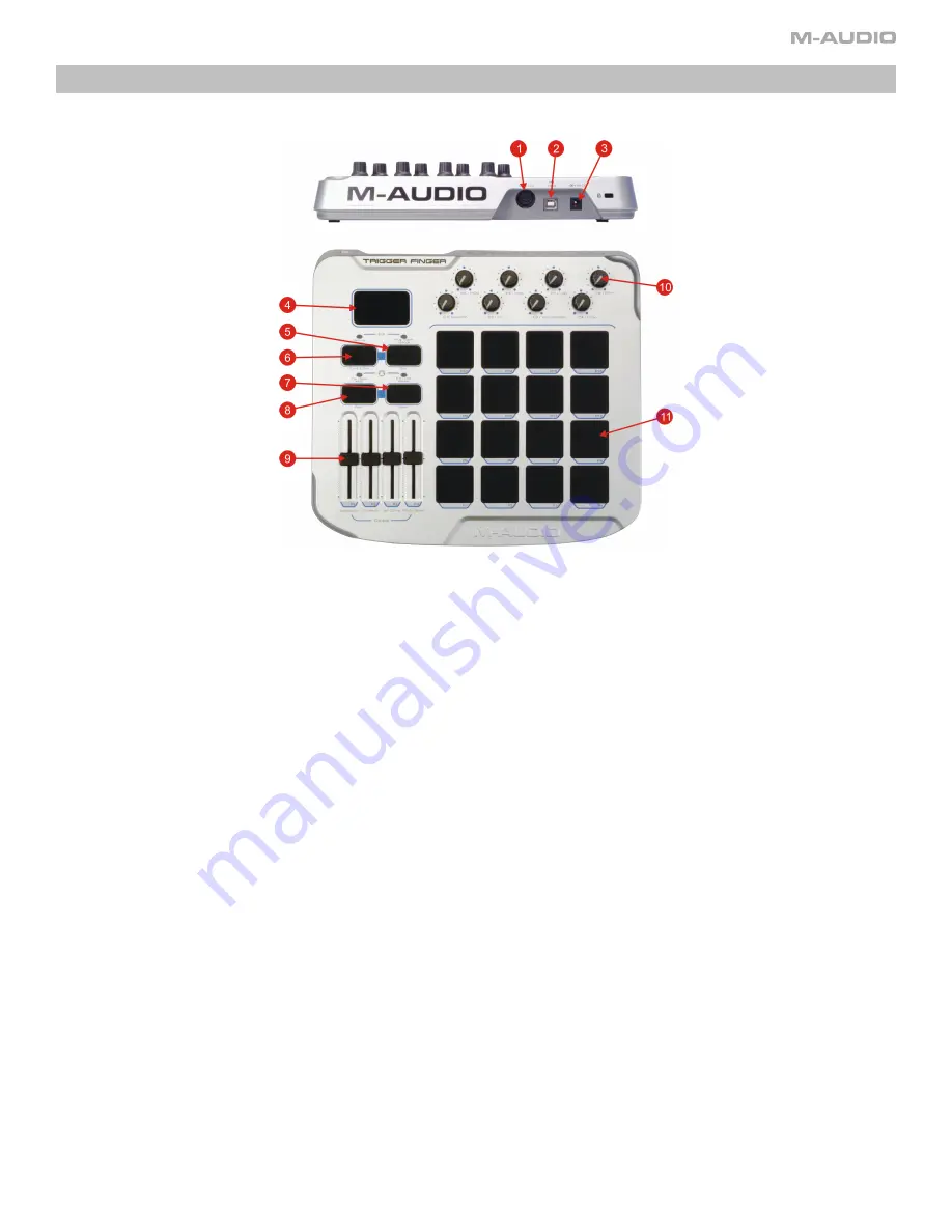
This section will familiarize you with the interface of the Trigger Finger. Please reference the image below when reading about each control.

1.   

MIDI Out Jack:

 This jack outputs MIDI information from either the Trigger Finger control surface or from the host computer.

2.   

USB Port:

 The Trigger Finger is connected to a host computer through this port using the supplied USB cable.

3.   

PSU Jack:

 When using the Trigger Finger while disconnected from a computer, an optional DC power supply can be connected to this jack in order to power 

the unit.

4.   

LED Display:

 This three-digit display will show the current memory location being used as well as values for the Trigger Finger’s various parameters.

5.   

Program / Bank Change / Exit Button:

 This button is used to send program/bank changes from the Trigger Finger. It is also used to exit the Edit Mode 

without saving your changes (more on this in the section titled “Editing the Trigger Finger”).

6. 

 Memory Recall / Save & Exit Button:

 This button is used to recall one of the 16 memory locations in the Trigger Finger. It will also save your edits when exiting 

Edit Mode.

7.   

Lock / Full Velocity / Select Button:

 This button cycles through the Trigger Finger’s two velocity control modes: Locked Velocity and Full Velocity. When editing 

the Trigger Finger, this button is used to select one of the 8 knobs for programming.

8.   

Ctrl / Note Mute / Peek Button:

 Pressing this button will cycle through the two Mute Modes available on the Trigger Finger: Control Mute and Note Mute. 

When editing the Trigger Finger, this button is used to view the current setting of a control without changing it.

9. 

 Programmable  Sliders:

  When  performing,  these  faders  will  transmit  MIDI  controller  information.  When  in  Edit  Mode,  these  faders  will  set  the  global 

parameters (more on this in the section titled “Editing the Trigger Finger”).

10. 

 Programmable Knobs:

 When performing, these knobs will transmit MIDI controller information. When in Edit Mode, these knobs are used to set the values 

(such as note, controller, and channel) for the Trigger Finger’s pads, sliders, and knobs (more on this in the section titled “Editing the Trigger Finger”).

11. 

 Programmable Pads:

 These 16 pads are velocity sensitive, meaning that they can sense how hard or soft they are struck. They are also pressure-sensitive, 

meaning they will transmit MIDI controller information based on how hard you press on the pads, similar to aftertouch on a keyboard. The pads are also 
used to recall and save memory locations (when used in conjunction with the Memory Recall Button) and to issue Program/Bank Changes (when used with 
the Prog/Bank Change Button).

Summary of Contents for Trigger Finger

Page 1: ...troller data and velocity data simultaneously Locked and Full Velocity Modes Selectable velocity curves Programmable with the Enigma Editing software included Memory presets for Reason Redrum Live Imp...

Page 2: ...er if you use multiple applications at once including applications that are ReWired together such as using Ableton Live as a host application and simultaneously running Propellerhead Reason as a slave...

Page 3: ...talled the Trigger Finger will appear in the computer as a simple MIDI device with one input port and one output port You will select the Trigger Finger input port as the MIDI input device in your aud...

Page 4: ...two velocity control modes Locked Velocity and Full Velocity When editing the Trigger Finger this button is used to select one of the 8 knobs for programming 8 Ctrl Note Mute Peek Button Pressing this...

Page 5: ...ill transmit its assigned MIDI note with the assigned On Velocity Lock value and assigned Off velocity value The Velocity On Lock value can be set individually for each pad in Edit Mode The Off value...

Page 6: ...channel used when the knob or slider transmits its data Range 0 to 16 0 Global MIDI Channel The process of programming the Trigger Finger s controls entails selecting a control to edit a pad knob or...

Page 7: ...a C chromatic scale changing this value to 2 will result in a D chromatic scale being sent when the pads are played Note that when the slider is positioned in the center the transpose value is 0 Globa...

Page 8: ...the effect of performing a factory reset Orange devices are your own user created devices You can create as many of these as you like simply by clicking on the button in the bottom left hand corner Th...

Page 9: ...from the pads The two valid CC assignments are explained below CC 147 Note On Off This CC setting results in the default behavior for the pads Pressing the pad will send a Note On message with the pl...

Page 10: ...Memory Presets Because of its extremely exible architecture there are many applications and uses for the Trigger Finger more than can be listed here However you will nd a few useful operation suggest...

Page 11: ...e features than you would if you just used Edit Mode on the unit itself One trick that will be available to you is the ability to assign no MIDI note to a pad just leaving its pressure control active...

Page 12: ...ey may save you from having to contact Technical Support Problem My Trigger Finger is not turning on Reason The Trigger Finger is not receiving power Solution If you are trying to power the Trigger Fi...

Page 13: ...872 0444 Technical Support Mac 1 800 638 2120 Technical Support fax 418 872 0034 Sales e mail infocanada m audio com Sales phone 866 872 0444 Sales fax 514 396 7102 Internet Home Page http www m audio...

Page 14: ...27 16 0 127 0 11 Hi Hat Closed F 1 127 OFF 0 127 24 0 127 0 12 Hi Hat Open A 1 127 OFF 0 127 25 0 127 0 13 Crash 1 C 2 127 OFF 0 127 32 0 127 0 14 Crash 2 A 2 127 OFF 0 127 40 0 127 0 15 Ride D 2 127...

Page 15: ...0 127 16 0 127 0 11 Hi Wood Block E 4 127 OFF 0 127 24 0 127 0 12 Low Wood Block F 4 127 OFF 0 127 25 0 127 0 13 Open Cuica G 4 127 OFF 0 127 32 0 127 0 14 Muted Cuica F 4 127 OFF 0 127 40 0 127 0 15...

Page 16: ...0 11 Bass drum C 1 87 OFF 0 127 24 0 127 0 12 Bass drum C 1 95 OFF 0 127 25 0 127 0 13 Bass drum C 1 103 OFF 0 127 32 0 127 0 14 Bass drum C 1 111 OFF 0 127 40 0 127 0 15 Bass drum C 1 119 OFF 0 127 4...

Page 17: ...0 127 16 0 127 0 11 Hi Hat A 1 127 OFF 0 127 24 0 127 0 12 Ride D 2 127 OFF 0 127 25 0 127 0 13 Bass Drum C 1 127 OFF 0 127 32 0 127 0 14 Snare D 1 127 OFF 0 127 40 0 127 0 15 Hi Hat Open F 1 127 OFF...

Page 18: ...10 Hi Hat F 1 88 OFF 0 127 16 0 127 0 11 Hi Hat F 1 100 OFF 0 127 24 0 127 0 12 Hi Hat F 1 127 OFF 0 127 25 0 127 0 13 Crash C 2 64 OFF 0 127 32 0 127 0 14 Crash C 2 88 OFF 0 127 40 0 127 0 15 Crash...

Page 19: ...OFF 0 127 16 0 127 0 11 Channel 11 F 2 127 OFF 0 127 24 0 127 0 12 Channel 12 E 2 127 OFF 0 127 25 0 127 0 13 Channel 13 F 2 127 OFF 0 127 32 0 127 0 14 Channel 14 G 2 127 OFF 0 127 40 0 127 0 15 Chan...

Page 20: ...Pattern 11 A 1 127 119 0 127 24 0 127 0 12 Pattern 12 B 1 127 119 0 127 25 0 127 0 13 Pattern 13 C 2 127 119 0 127 32 0 127 0 14 Pattern 14 C 2 127 119 0 127 40 0 127 0 15 Pattern 15 D 2 127 119 0 12...

Page 21: ...ound 6 F 1 127 OFF 0 127 9 0 127 0 11 Sound 6 F 1 127 OFF 0 127 10 0 127 0 12 Sound 5 E 1 127 OFF 0 127 11 0 127 0 13 Sound 7 F 1 127 OFF 0 127 12 0 127 0 14 Sound 8 G 1 127 OFF 0 127 13 0 127 0 15 So...

Page 22: ...127 0 11 Sound 6 F 1 127 OFF 0 127 10 0 127 0 12 Sound 5 E 1 127 OFF 0 127 11 0 127 0 13 Sound 7 F 1 127 OFF 0 127 12 0 127 0 14 Sound 8 G 1 127 OFF 0 127 13 0 127 0 15 Sound 8 G 1 127 OFF 0 127 14 0...

Page 23: ...7 0 127 9 0 127 11 11 Drum Cell 3 E 3 127 117 0 127 10 0 127 11 12 Drum Cell 4 F 3 127 117 0 127 11 0 127 11 13 Drum Cell 5 G 3 127 117 0 127 12 0 127 11 14 Drum Cell 6 A 3 127 117 0 127 13 0 127 11 1...

Page 24: ...0 127 1 11 Synth Loop 3 D 2 127 119 0 127 10 0 127 1 12 Synth Loop 4 D 2 127 119 0 127 11 0 127 1 13 Chicago Bass Lp E 2 127 119 0 127 12 0 127 1 14 Staccato Bass Lp F 2 127 119 0 127 13 0 127 1 15 B...

Page 25: ...F 2 127 119 0 127 24 0 127 0 12 G 2 G 2 127 119 0 127 25 0 127 0 13 A 2 A 2 127 119 0 127 32 0 127 0 14 B 2 B 2 127 119 0 127 40 0 127 0 15 C 3 C 3 127 119 0 127 48 0 127 0 16 D 3 D 3 127 119 0 127 56...

Page 26: ...127 0 11 808 pattern 7 F 2 127 OFF 0 127 10 0 127 0 12 808 pattern 8 G 2 127 OFF 0 127 11 0 127 0 13 808 pattern 1 A 2 127 OFF 0 127 12 0 127 0 14 808 pattern 2 B 2 127 OFF 0 127 13 0 127 0 15 808 pa...

Page 27: ...1 127 OFF 0 127 9 0 127 0 11 Syn1 pattern 7 B 1 127 OFF 0 127 10 0 127 0 12 Syn1 pattern 8 C 0 127 OFF 0 127 11 0 127 0 13 Syn1 pattern 1 F 1 127 OFF 0 127 12 0 127 0 14 Syn1 pattern 2 F 1 127 OFF 0...

Page 28: ...7 0 12 5 E 1 127 OFF 0 127 11 0 127 0 13 7 F 1 127 47 0 127 12 0 127 0 14 8 G 1 127 48 0 127 13 0 127 0 15 8 G 1 127 OFF 0 127 14 0 127 0 16 7 F 1 127 OFF 0 127 15 0 127 0 Fader Control CC Data 1 Data...

Page 29: ...27 0 11 A 1 A 1 127 OFF 0 127 24 0 127 0 12 B 1 B 1 127 OFF 0 127 25 0 127 0 13 C 2 C 2 127 OFF 0 127 32 0 127 0 14 C 2 C 2 127 OFF 0 127 40 0 127 0 15 D 2 D 2 127 OFF 0 127 48 0 127 0 16 D 2 D 2 127...

Page 30: ...onal control MIDI cc Description Data 1 Data 2 0 119 Standard MIDI cc s 120 127 Channel Mode Messages 128 Pitchbend Sensitivity 129 Channel Fine Tune 130 Channel Coarse Tune 131 Channel Pressure 132 R...

Page 31: ...4 105 A 6 10 A 2 42 F 1 74 D 4 106 A 6 11 B 2 43 G 1 75 D 4 107 B 6 12 C 1 44 G 1 76 E 4 108 C 7 13 C 1 45 A 1 77 F 4 109 C 7 14 D 1 46 A 1 78 F 4 110 D 7 15 D 1 47 B 1 79 G 4 111 D 7 16 E 1 48 C 2 8...

Page 32: ...speci c product Warranty Registration Thank you for registering your new M Audio product Doing so immediately both entitles you to full warranty coverage and helps M Audio develop and manufacture the...

Reviews: