


8
Front and Back Panel
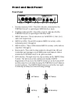
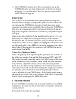
Front Panel
(insert Front Panel fig 1. here)
1. Interface indicator LED - This LED, when lit, indicates that the
PORTMAN 4x4/S is operating in MIDI Interface mode.
2. Patchbay indicator LED - This LED, when lit, indicates that the
PORTMAN 4x4/S is operating in Patchbay mode.
3. MIDI Connectors - These connectors are for MIDI In 1, Out 1, In 2,
and Out 2 respectively.
4. MIDI Out LEDs - These LEDs indicate MIDI Out activity on the
indicated ports (1 through 4).
5. MIDI In LEDs - These LEDs indicate MIDI In activity on the indicat-
ed ports (1 through 4).
6. Reset switch - This switch, when pushed, will send Note Off and
Controller reset messages on all MIDI ports and channels. It then
returns the PORTMAN 4x4/S to its previous mode.
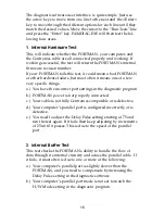
7. DIP switches - The right most two dip switches set the SMPTE Write
Format. The left most switch enables and disables SMPTE
Regeneration. Please note: the SMPTE format set on the Format DIP
switches may be overridden by using the PORTMAN 4x4/S Remote
Control software. The SMPTE Write format, as set by the two right
Format dip switches, have the following settings:
put dip switch Write format figure here
I
N
1
O
UT
1
I
N
2
O
UT
2
M
IDI
M
IDI
O
UT
W
RITE
R
ESET
R
EAD
R
EGEN
W
RITE
P
ATCH
I
NTER
M
IDI
I
N
1
2
3
4
l
Portman 4x4/S
PC MIDI INTERFACE/SMPTE SYNC
F
ORMA
T
R
EGEN
O
N
O
FF
1.
2.
3.
4.
5.
6.
7.
8.
9.
10.
24 Frames
25 Frames
F
ORMA
T
O
N
O
FF
F
ORMA
T
O
N
O
FF
30 Drop
30 Non-drop
F
ORMA
T
O
N
O
FF
F
ORMA
T
O
N
O
FF


