


12
Hardware Inputs (ANALOG 1/2 IN, S/PDIF IN)
The
Mixer
page also provides software level control for routing, mixing and direct monitoring of the FireWire Solo’s analog and S/PDIF digital
inputs. These pairs are labeled
analog 1/2 in
and
spdif in
.
Channel Control Features
Output Routing Buttons
Each of the four stereo pairs may be assigned to any of the FireWire Solo’s analog or digital outputs by clicking on the output button of the
desired output pair. These are labeled
1/2
(the FireWire Solo’s analog Line Outputs) and
spdif
(the FireWire Solo’s S/PDIF Outputs). Any or both
Mixer output pairs may be selected (the button’s outline turns dark gray when active). These channels’ output signals appear at the selected
output buses, shown in the
Output Bus
box in the lower left corner. If multiple Mixer channels are assigned to the same output pair, the signals
will be summed at the assigned output. Note that clipping of summed signals is possible, so keep an eye on your output level meters when
summing mixer channels.
Stereo Link Button
Input levels from each stereo pair are controlled by software faders; pairs can be linked for stereo operation by clicking the channels’
Link
button. The button turns blue when active. Once the channel is linked, grabbing and moving one fader will move both faders in unison.
Mute Button
Selecting the
mute
button (the button turns red) will cause that channel pair to cease audio output. Deselecting the
mute
button will resume
audio output on that channel pair.
Solo Button
Selecting the
solo
button (the button turns yellow) will cause all other channels to cease audio output; deselecting the
solo
button will resume
audio output on all channels. Multiple solo selections are possible.
Panning Controls
The Hardware Input channel pairs also offer virtual
Pan
pot controls. As with any typical mixer, the
Pan
works in conjunction with the output
assign buttons to enable you to route the signal as you wish.
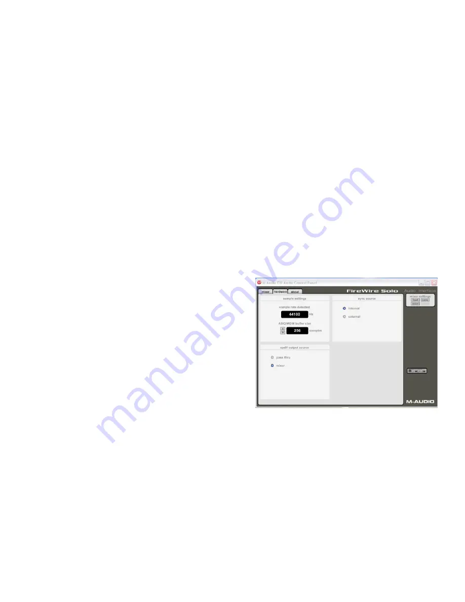
Hardware Page
The Hardware page gives you access to important information and functions
of the FireWire Solo.
Sample Rate Detected
This field displays the
currently-detected sample rate from the currently
selected incoming sync source
.
ASIO/WDM Buffer Size
In this field you can select the buffer size you wish to work with. Smaller
buffer sizes result in lower latency (“latency” refers to the time it takes for
your input signal to pass through your audio software and appear at the
outputs), but may not function well with slower systems. The default buffer
size setting is 256. This setting may adequately serve your purposes, but
if you wish to, you can experiment with lower settings. If you experience
stuttering or crackling in your audio playback, try using a larger buffer
size.
NOTE
:
This section does not apply to Mac OS X, and will not appear if you are running that operating system.
Sync Source
This field allows you to choose between the FireWire Solo’s INTERNAL clock and an EXTERNAL clock source. INTERNAL selects the incoming clock
from the FireWire bus as set by your audio software. Use EXTERNAL when you wish to record from the S/PDIF inputs, or otherwise lock to the
sample rate from an external S/PDIF source.
S/PDIF Output Source
Selecting “mixer” routes the signals assigned to the S/PDIF output from the control panel mixer to the S/PDIF output. Selecting “Pass Thru”
allows a surround encoded stream such as AC3 or DTS to be sent to the S/PDIF output.