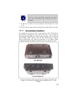
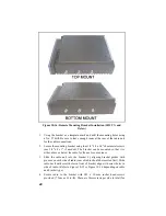

50
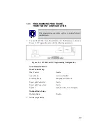
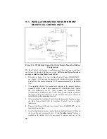
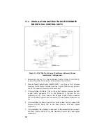
11.3 INSTALLATION INSTRUCTIONS FOR FRONT
MOUNT DUAL CONTROL UNITS
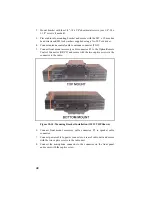
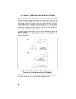
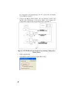
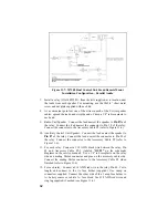
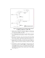
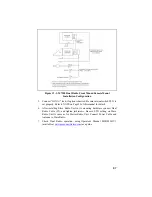
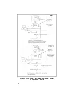
Figure 11-6: M7100 Dual Control Unit Front/Remote Mount Installation
Configuration
The Dual Control Unit feature is configured such that only one control unit
can be used for Extended Option accessories.
All Extended Option functions
are only available at the Main Control Unit.
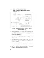
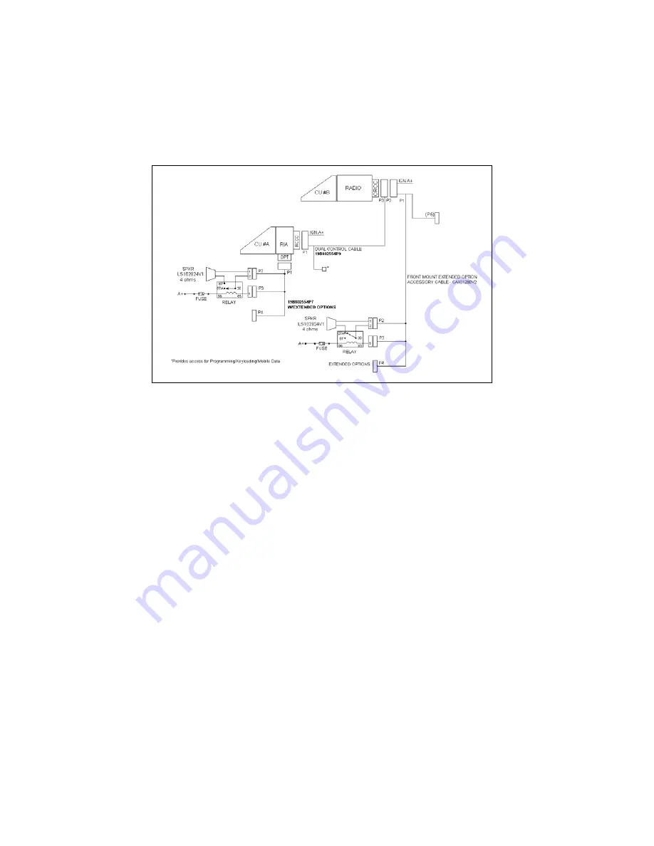
1. Referring to Figure 11-6, run the Dual Control Cable (19B802554P9 –
see Figure 11-8) between locations for the Radio Unit and Auxiliary
Control Unit. Be sure to locate the P2/P3 connector assembly at the Radio
Unit.
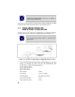
2. After installing Radio Unit mounting hardware in the normal fashion,
connect the Dual Control Cable connector (P3) to the Radio Unit. Tighten
the two jackscrews on P3. Next, connect the Accessory Cable
(CA101288V2) Connector (P1) to the Dual Control Cable Connector
(P2), and tighten the jackscrews on P2. Connect the power cable, and
install Radio Unit in mounting bracket.
3. After installing the Auxiliary Control Unit in the normal fashion, connect
the Dual Control Cable (P1) to Auxiliary Control Unit, and tighten
jackscrews.
4. Connect the Remote Mount Accessory Cable (19B802554P7) to the
Auxiliary Control Unit.
5. A yellow Ignition Sense lead is provided on the Dual Control Cable and
the Front Mount Accessory Cable. If the
“Ignition Sense”
feature is
enabled on the Radio Unit, it is necessary to connect only one of the
Summary of Contents for P5100 Series
Page 1: ...Installation Product Safety Manual MM102342V1 Rev Fp1 Sep 07 M7100IP Series Mobile Radio...
Page 17: ...17 Figure 7 2 Rear Angle View of Radio 110W VHF Shown Figure 7 3 Interface Cables...
Page 18: ...18 Figure 7 4 Option Cables...
Page 27: ...27 Figure 10 4 Front Mount Extended Option Accessory Cable CA101288V2...
Page 31: ...31 Figure 10 6 Remote Extended Option Control Cable CA101288V4...
Page 64: ...64 Figure 12 3 Dual Radio Configuration Front Remote Mount PC Programming Procedure...
Page 66: ...66 Figure 12 4 Dual Radio Configuration Remote Remote Mount PC Programming Procedure...
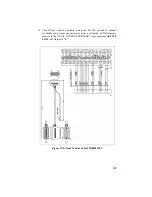
Page 67: ...67 Figure 12 5 Dual Radio Control Cable CA101288V10...
Page 71: ...71 NOTES...