41
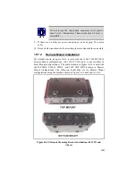
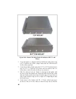
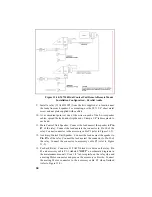
the 50W TX and Below radios and four screws per side (8 total) for the
60W TX and Above radios.
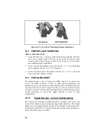
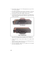
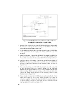
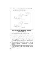
5. Connect antenna coaxial cable to antenna connector (TNC).
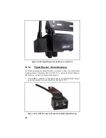
6. Connect remote control cable connector P1 to the ORCC connector on
the radio unit and secure with the two captive screws.
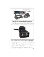
7. Connect other end of remote control cable to the remote control cable
connector (RCCC) on the remote control unit.
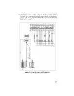
8. Connect remote mount accessory cable connector P1 to the option
connector (OPT) on control unit. Then connect the speaker to connector
P2 and accessory connector P3 to any options (hookswitch, etc.). If
connector P3 is not used, insulate and tie back to main cable.
9. Recheck all connections and cables. Insert fuse into transmit fuse
assembly.
Summary of Contents for P5100 Series
Page 1: ...Installation Product Safety Manual MM102342V1 Rev Fp1 Sep 07 M7100IP Series Mobile Radio...
Page 17: ...17 Figure 7 2 Rear Angle View of Radio 110W VHF Shown Figure 7 3 Interface Cables...
Page 18: ...18 Figure 7 4 Option Cables...
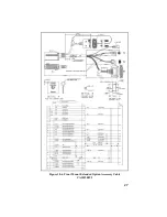
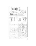
Page 27: ...27 Figure 10 4 Front Mount Extended Option Accessory Cable CA101288V2...
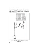
Page 31: ...31 Figure 10 6 Remote Extended Option Control Cable CA101288V4...
Page 64: ...64 Figure 12 3 Dual Radio Configuration Front Remote Mount PC Programming Procedure...
Page 66: ...66 Figure 12 4 Dual Radio Configuration Remote Remote Mount PC Programming Procedure...
Page 67: ...67 Figure 12 5 Dual Radio Control Cable CA101288V10...
Page 71: ...71 NOTES...

