background image

FES Maintenance manual Version 1.12  

September 2016 

Page 10 of 26 


3.2.5 Wirings 


FES  wiring  consists  of  power,  signal  and  12V  wires,  and  different  types  of 

connectors. 
For power cables we use high quality Betatherm 155 wires with cross section of 35 sqmm. 
For signal wires we use high quality tinned and shielded wires. For all 12V circuits we use 
aviation grade Spec 55 wires.  
 

On  the  end  of  power  wires  are  pressed  and  soldered  suitable  cable  shoes  and 

Radsok  power  connectors.  Signal  wires,  are  soldered  to  multipole  DB9  or  DB15 
connectors, and on other side directly to FCC box electronic circuit board. 12V circuits are 
equipped with cables shoes. 
 

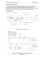
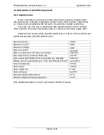
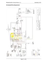
-DC/DC  converter  is  used  to  convert  high  voltage  from  FES  battery  packs,  to  12V 

which  is  used  to  supply  instruments,  and  main  contactor.  It  also  charge  12V  battery  if 
installed. 
 

-Main  contactor  is  used  to  connect  and  disconnect  traction  batteries  (FES  battery 

packs) to motor controller. There is installed also precharge resistor.  
 

-Motor  controller  is  used  to  convert  high  voltage  DC  to  three  phase  AC  voltage 

which  goes  to  motor.  It  also  send  RPM  and  controller  temperature  by  CAN  bus  to  FCU 
instrument. 

-Ventilators are used to cool down motor controller. 


-Power switch (double pole) is used to give 12V power to main contactor, supply to 

electronic circuit board in motor controller. 
 

-BMS inside of battery packs is used to balance and to control charging. It can be 

connected  to  PC  with  a  special  cable  in  order  to  monitor  charging  process  with  BMS 
Control software. During flight BMS is sending data to FCU instrument, about temperature 
of the pack and voltage levels of each cell. 
 

-Shunt is used to measure current from Battery packs. 


-LXUI  box  convert  analog  measurement  of  current  and  voltage  to  digital  signal 

which is sent by CAN bus to FCU instrument. 
 

-FCC  box  have  electronic  circuit  board,  where  all  signal  and  12V  wires  came 

together and are spitted to right directions. It consist also a microprocessor for automatic 
propeller  positioning.  There  is  located  also  2A  fuse,  potentiometer  for  adjusting  of 
electronic braking and DB9 female connector for FCU update.  
 

-12V battery is not really required for operation of FES system, but is there mainly 

to be able to set other instruments if main battery packs are still charging. Battery should 
be equipped with 3A fuse. 
 

-325A power fuse protect the whole system in case of a high power short-circuit. 
-Battery packs provide power to the whole FES system 


-one  1,kW  or  optionally  two  600W  external  chargers  are  used  for  charging  of 

Battery packs, one by one or simultaneously in case of two chargers. 
 

-FCU instrument gives information to the pilot about important parameters. There is 

also located throttle knob, and 3 bright LEDs in red and green color. 


Summary of Contents for AS 13

Page 1: ...ailplane types LAK17A FES LAK17B FES MiniLAK FES Silent 2 Electro FES AS 13 5m FES HPH 304ES FES Discus 2c FES Ventus 2cxa FES LZ design d o o Brod 3D 1370 Logatec Slovenia tel 386 59 948 898 info lzd...

Page 2: ...S test run on the ground 13 4 2 3 After flight inspection 14 4 2 4 Ground handling 14 4 2 5 Tie down and ground towing 14 4 2 6 Storing and transportation 14 4 2 7 Cleaning and clean keeping 15 4 2 8...

Page 3: ...bility and warranty for installation and failures of components which could be result of improper installation even if they occur later during normal use if the cause of a failure is with wrong instal...

Page 4: ...irements of CS 22 1529 for sailplane maintenance 2 1 Warnings cautions and notes The following definitions apply to warnings cautions and notes used in this manual Warning Means that the non observati...

Page 5: ...but also that it would need as little as possible of maintenance However some minimal maintenance is still required In order to be able to perform maintenance it is first required to know locations o...

Page 6: ...phase current which supply motor Electrical motor power ratings type FES LAK M100 at 116V on motor controller and loaded with propeller type FES LAK P10 100 Maximum torque 75 Nm Maximum current 200A...

Page 7: ...light Operating conditions the propeller can be operated in any normal environment conditions except hail sand storm or similar FES propellers as described herein is designed and tested according to C...

Page 8: ...cation 1 RPM input 2 LED INPUT 1 digital output for BRAKE 1 analog output for POWER adjustable with rotary knob 4 temperature Controller Motor 2 battery Audio signal 1 analog input for measuring curre...

Page 9: ...ed with 16 LEDs to monitor its operation For and terminals GEN2 packs only we chose to use Amphenol Radsok hyperbolic high power contact technology High current female contacts are hidden inside of th...

Page 10: ...supply to electronic circuit board in motor controller BMS inside of battery packs is used to balance and to control charging It can be connected to PC with a special cable in order to monitor chargin...

Page 11: ...FES Maintenance manual Version 1 12 September 2016 Page 11 of 26 3 3 General FES wiring scheme...

Page 12: ...Keep magnetic memory cards or electronic devices out of the rotor s close up range because the strong magnetic field can cause a delete of data Be also careful with medical devices e g pacemakers whi...

Page 13: ...should be performed a pre flight inspection Check the sailplane itself as requested before a flight Perform FES test run on the ground as described below 4 2 4 FES test run on the ground 1 Remove prop...

Page 14: ...ifting When opening and closing the canopy propeller blades must be always positioned horizontaly 4 2 5 Tie down and ground towing Do not leave FES equipped sailplane outside on the rain unless it is...

Page 15: ...upported in a fuselage dolly positioned just forward of the main landing wheel opening Forward stop or a belt must be provided for the fuselage dolly in order to prevent slipping forward and leaving t...

Page 16: ...y pack 8 Fix temperature sensor cable to the side of battery compartment box 9 Un tighten battery pack fixation knobs 10 Take the fixation plate out 11 Firmly grip the front battery by a carrier strap...

Page 17: ...r cables Before disconnection is recommended to mark them as A B C and draw their position against each other on list of paper 5 Un secure six M8 bolts and unscrew them out One of M8 bolts which is be...

Page 18: ...1 12 September 2016 Page 18 of 26 Braking of propeller works OK FCU instrument is functioning properly 4 4 3 Mounting and removal of the propeller For mounting and removal of the propeller blades ref...

Page 19: ...slightly lubricated ventilation valve pin which goes trough the shaft of motor should be very slightly lubricated so that travels forward and backward easily under spring pressure Avoid of too much l...

Page 20: ...ng in a hangar or in a trailer 5 3 Inspection after every 100 flight hours Apart of required check list for the glider after every 100 flight hours it is necessary to check also thoroughly the FES sys...

Page 21: ...ing or after ground loop check Battery packs if there is any visible damage check the FCU instrument for proper operation check if there is any damage on the propeller blades in case they touched the...

Page 22: ...placards Maximum speed to fly with motor running 8 Balancing of rotating parts In order to have a smooth run of FES complete assembly of motor spinner and propeller blades are balanced to vibration l...

Page 23: ...ck power switch flip it OFF an ON a few times When you are reporting a problem please describe the problem and its behavior as much as possible accurately It might be helpful for you and also for us i...

Page 24: ...ller pins with spacer crown nut and safety pin propeller holder composite covers FCU instrument FCC FES electronic circuit plate main contactor power switch or key switch motor controller motor 2A fus...

Page 25: ...wiki Soldering_iron keep the iron tip clean A clean iron tip means better heat conduction and a better joint use a wet sponge to clean the iron tip between soldering of joints keep the iron tip well...

Page 26: ...ual Version 1 12 September 2016 Page 26 of 26 10 Revision history October 2013 Initial release of Maintenance manual v1 0 November 2013 Minor updates v1 1 June 2015 Minor updates v1 11 September 2016...

Reviews: