background image

H-6800  Conference set  User manual


C) 

CONNECTION 


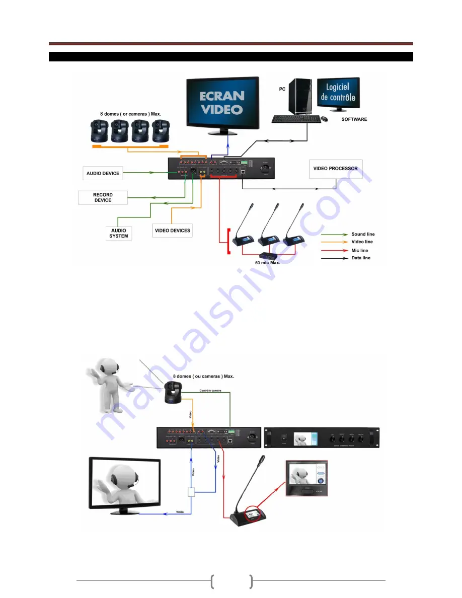
Video devices can be : camera output, DVD player, Blueray outpur, MP4 player output or computer(video output)  

Sound devices can be : CD player, MP3 player, Tape player, computer ( sound output ) or a mixer 

Record devices can be : Mp3 recorder, Tape recorder, a computer sound input,... 

Sound system can be : Power amplifier / Mixer. 


The main unit can control up to 50 mic. If you want to control more than 50 mic, you must to use extension power supply                     
( in option ). 


Important :  

You cannot display on mic the video from camera. If you want to display , please connect Video output (RCA) to DVD1 or DVD2 (RCA). 
If you want display the camera video both on Video screen and mic LCD, please use video distributor (video input)  connect to Video output 
(RCA), then connect vieo distributor (video out) to main unit DVD 1 or DVD2 (RCA )input and extral Video screen( such as projector, TV)  


Summary of Contents for H-6800

Page 1: ...H 6800 Conference set User manual 1 ...

Page 2: ...deo 11 G Auto track function 12 H Technical specifications 13 I Operation of Software 15 a System Setting 17 i Basic setting 17 ii Video Setting 18 iii Venue Configuration 19 b Line Detect 21 c Preparation 22 i Create Edit Conference 22 ii Create Edit Proposal 23 iii Create Edit Delegate Data 24 d Start Conference 25 i Discuss 25 ii Sign In 26 iii Start Ballot 27 iv Documents 29 v Insert Display 3...

Page 3: ...eos from camera or external video devices Built in speaker on mic and main unit 3 conference mode mode free mode FIFO mode limit 1 to 9 mic in same time Mode vote yes no abstain Mode elect up to 5 candidates Mode score 1 aux input RCA 1 line output RCA 1 rec output RCA 1 master output XLR 2 DVD video inputs RCA 8 cameras or domes inputs RCA 2 auto tracking cameras control 2 video output BNC 5 mic ...

Page 4: ... of the speaker 5 MASTER LEVEL CONTROL Main unit have a master output to send conference sound to an external sound system This button is used to adjust the level of the line rec master output 8 9 10 6 MIC SPEAKER LEVEL CONTROL The mic are composed of built in speakers This button is used to adjust the maximum volume level of these speakers Rear panel 7 AUX IN INPUT Aux level type Connect on this ...

Page 5: ...cable 220V The fuse is used to protect the main unit If the fuse use is defect replace it by a fuse with same size and same value 16 CAMERA CONTROLE CONNECTOR If you use dome in place of camera you can control pan and tilt move directly from software Connect this socket to the control connector of domes Note To know connections read the user manual of the dome 17 PC CONNECTOR Connect this socket t...

Page 6: ...ed also to enter in all the menu Microphone speaker volume LCD contrast video 4 ON OFF BUTTON This button is used to switch the mic on or off 5 BUILT IN SPEAKER All the mic are composed of a built in speaker You can adjust the volume of this speaker directly on the system setup menu 6 HEADPHONE CONNECTOR This socket is used to connect a headphone When you connect a headphone the built in speaker w...

Page 7: ... amplifier Mixer The main unit can control up to 50 mic If you want to control more than 50 mic you must to use extension power supply in option Important You cannot display on mic the video from camera If you want to display please connect Video output RCA to DVD1 or DVD2 RCA If you want display the camera video both on Video screen and mic LCD please use video distributor video input connect to ...

Page 8: ...OFF button A When the mic is on the light on goosneck mic is on red light Push another time the ON OFF button A to switch off the mic Touch the LCD enter in the menu of delegate mic You can setup volume contrast of LCD and video The chairman mic have the same operaing as delegate mic but the chairman mic have the priority button B When you push the priority button B you switch off all the delegate...

Page 9: ...Video Note a The main unit LCD will display video if there has video input the system DVD1 DVD2 touch the LCD to enter the main menu b Please select the video input by VIDEO A VIDEO B c The main unit LCD will display the standby picture if there has no video input the system touch the LCD to enter the main menu and select the video input c LCD Contrast You have the choice between 3 modes Free mode...

Page 10: ...to all the delegate mic When all the mic ID are affected press on the button Back for exit of the menu Microphone This message is displayed on all the microphone touch screen Press the on off button of the corresponding mic to the affected the number The other mic are always this message posted but with an incremented number of a unit Press then on button on off of the mic concerned and so on unti...

Page 11: ... also adjust the volume of each desk individually Press on the buttons and touch screen to increase or decrease the volume of the speaker then press on button Back to leave the menu You can adjust the contrast of the touch screen Push and buttons to adjust then push Back button if you want to leave menu without save the setup If there has video input from main unit microphone LCD will display the ...

Page 12: ... 3 delegates The video is porvided by a dome connected and controled by the main unit The main unit is conneted to an external video screen When the chairman mic 1 switch his mic on the dome will be moved directly on him so the chairman is display on all the mic touch screen and on the video screen figure 1 When the delegate mic 2 switch his mic on the dome will be moved directly on him so the del...

Page 13: ...s are automatics but the place of mic must be setup You need to connect the system to a computer to setup the place of all the mic When the preset are saved you can disconnect the computer We will explain you the operating of the auto track function IMPORTANT Cameras cannot be displayed directly on touch screen You must to connect video output to DVD input 1 or 2 to show video from cameras on touc...

Page 14: ...Max resolution LCD 480x272 LCD type 4 3 24 bit TFT Dimensions 488 x 84 x 324mm 19 2U Power supply 220V 50Hz Fuse 8A 250V N Weight 8Kg Microphone Connector DIN 8P Cable 3m Headphone output Mini Jack Rec output Mini Jack Talking distance 20 50cm Frequency response 40Hz 16 KHz Sensitivity 44dB 2dB S N ratio 85dB Max resolution LCD 480x272 LCD type 4 3 24 bit TFT Gooseneck mic 41cm 17 Consumption 2W D...

Page 15: ...mes or cameras to the video inputs RCA Connect domes control output to all the domes Connect the video output to a DVD input 1 or 2 You can connect the main unit to an external video screen If you want to display video output directly on you computer it must be composed of a video capture card The connection between main unit and domes depends of the norm of communication Protocol of the domes You...

Page 16: ...cted to the computer and switch the main unit on Start the software If the main unit is not connected an alert message will be displayed on computer screen If the main unit is connected to the computer a panel will be displayed and you must to enter the password to enter in the software The password is 1234 Enter the password and push the login button Software Main Interface There are seven parts ...

Page 17: ...e will switch to Venue Configuration interface and refresh the microphone icon quantity Operator can move the microphone icon if necessary 2 Chairman number setting Please set the correct chairman microphone number according the system 3 COM Port Setting Communication port should be within the setting or the operator can not enter the software Default port setting is from 1 to 10 4 Sub Screen Sett...

Page 18: ...home image then click video home icon to save the preset 5 Repeat the operation to finish all microphones preset 6 If operator wants clear the preset data please click Default then software will delete all preset datas 7 Please click Preview to check the preset and un preset microphone address 8 Operator can open or close the video in software when preset microphone 9 If system use more than 1 cam...

Page 19: ...guration Operator can set meeting place and seats according to the real situation 1 Create Seat Please click Create Seat icon system will create the microphone icon automatically icon quantity will same the microphone number that operator set in basic setting interface operator also can defined the icon configuration by Operator defined such as row quantity level Apeak distance ...

Page 20: ... Basic Setting seats setting will change after click Refresh Seat For example System Number Setting 100 Row 15 Level 11 Apeak 25 The seat configuration will as following 3 Import Configuration Please click Import Configuration to choose the bmp format picture as following Operator can make the configuration picture with the real situation of conference room Warning The software can not import the ...

Page 21: ...n and them click left mouse button again to fix up Mic icon After operator move all Mic icon to the correct position please click Fixup Mic Icon to finish the setting D System Setting Exit Please click Exit to exit the System setting interface back to software main interface b Line Detect 1 Click Line Detect to enter the system detect interface click icon to detect the microphone connection status...

Page 22: ...Conference Heading Please choose one conference heading that operator want edit and then click Edit Conference heading operator can edit the conference data in the text box then click Save to save the conference data after finish edit 3 Delete Conference Heading Please choose one conference heading that operator want delete and then click Delete Conference Heading the conference heading will delet...

Page 23: ...posal Choose one proposal listed in the software then click Delete Proposal to delete this proposal 3 Edit Proposal Choose one proposal listed in the software and then click Edit Proposal operator can edit the proposal information in the text box please click Save after operator finish edit the proposal information If the proposal is elect mode after choose this proposal click Candidate List to ed...

Page 24: ... will display in the software please edit the delegate s data in the textbox and click Edit to save the data 3 Delete Delete All Choose one delegate S N or name listed in the software then click Delete to delete this delegate s data Delete All means all delegate listed in the software will deleted 4 Load Save Data If software already include delegate s data please click Save Data system will pop u...

Page 25: ...time Choose the number of active delegate mic 1 to 8 mic For example if you setup 3 only 3 delegates mic plus the chairman mic can be active in same time This limit is not available for chairman mic c FIFO In this mode you can adjust the max number of simultaneous delegates between 1 to 8 Choose the number of active delegate mic 1 to 8 mic For example if you setup 2 only 2 delegates mic plus the c...

Page 26: ...w Click Close Video Window back to discuss interface B Start Conference Sign In Please click icon Sign In on the left side of the software to enter conference sign in interface 1 Expected Number Please setting the correct expected number of the vote elect scoring and then confirm 2 Quorum Rate Please setting the quorum rate of the delegation and then confirm 3 Sign In Please click Sign In Start an...

Page 27: ...s function only use for vote elect can not use 3 Start Vote Elect Operator can start ballot after setting the time and pass rate please choose one proposal that operator want ballot then start 4 End Vote Elect After ballot end result will display on both software and sub screen a The system will end the ballot and display result automatically if operator setting the limit time b If operator select...

Page 28: ...ar Ballot results will display in bar type in the software c Pie Ballot results will display in pie type in the software Operator can send the results to sub screen after choose the display type 8 Click exit back to conference start interface ...

Page 29: ...the documents content will pause with the setting symbol b Clew Speed This function only use for documents auto reading The documents auto reading speed will follow the clew speed setting with the pause symbol c Clew Color Set the color of clew sentence d Font Color Set the color of documents content e Font Setting 2 Documents Reading a Open Click Open to choose the document document should be in ...

Page 30: ...change to clew color Both software and sub screen will display the clew sentence d Auto Reading Click Auto the icon will change to Pause The document content will move to next sentence by the pause symbol that operator setting in software one by one Moving speed is the clew speed that operator setting in software sentence will change to clew color Click Pause Auto reading will stop icon will chang...

Page 31: ...elegates data in the list please click Save system will pop up one text box operator can save the sign in results in excel format This function is null if the list does not include any delegates information 5 Back Back to heading management interface Note Please make sure the software Preparation Create Edit Delegate Data part already include the delegate data or the sign in report list can not di...

Page 32: ...will display the proposal title that already balloted 3 Save Save the results as excel file 4 Print Software will display all ballot reuslt if operator use this function he she can use or to select the proposal results 5 Back Back to heading management interface f Help Operator can get software usage information with help file g Exit Exit the software ...

Reviews: