background image

Rev #37 

Version 8.0


April 2021


Page 21 of 121 

4.5


User Input 

The LXNAV S8x/S10x user interface consists of dialogues which have various input controls.  
They are designed to make the input of names, parameters, etc., as easy as possible.  Input 
controls can be summarized as: 


Text editor 


Spin controls (Selection control) 


Checkboxes 


Slider control  

To move the function from one control to another, rotate the lower rotary knob as follows: 


Clockwise rotation will select the next control. 


Counter  clockwise  rotation  will  select  the  previous  control.    The  lower  PUSH  button 
enters the selected feature. 


Faster rotation of the rotary knob will increase the rate at which the value changes i.e. 
bigger steps in value. 

4.5.1


Text Edit Control 

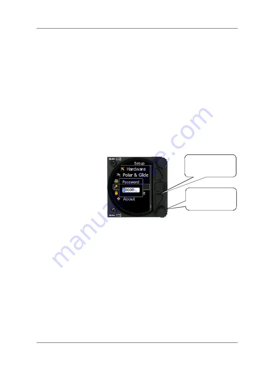
The  Text  Editor  is  used  to  input  an  alphanumeric  string;  the  picture  below  shows  typical 
options when editing text/numbers.  Use the lower rotary knob to change the value at the 
current cursor position.  


Once  the  required  value  is  selected,  press  the  lower  push  button  to  move  to  the  next 
character selection.  To move back to the previous character, press the upper push button.  
When you have finished editing, press the Enter key – the lower rotary button.  A short press 
of the middle push button exits from the edited field (“control”).  

Rotate the rotary 
knob to change the 
value 

Press the push 
button to move to 
the next character 

Summary of Contents for S10 Series

Page 1: ...April 2021 www lxnav com USER MANUAL S8x S10x Digital speed to fly variometer final glide calculator and navigational system with simple moving map Version 8 0 ...

Page 2: ......

Page 3: ...9 4 2 Rotary Switches 19 4 3 Buttons Three 20 4 4 Switching on the Unit 20 4 5 User Input 21 4 5 1 Text Edit Control 21 4 5 2 Spin Control 22 4 5 3 Selection Control 22 4 5 4 Checkbox and Checkbox List 22 4 5 5 Slider Selector 23 4 6 Switching Off 23 5 Operating Modes 24 5 1 Quick Access Menus 25 5 1 1 MC BAL 25 5 1 2 Reset G 25 5 1 3 Layout 25 5 1 3 1 Layout in the Numerical Page 26 5 1 3 2 Layou...

Page 4: ... 7 1 1 QNH 44 5 7 1 2 Safety Altitude 44 5 7 2 Flight Recorder 44 5 7 2 1 Recording Interval 44 5 7 2 2 Auto Finish 45 5 7 2 3 Finish Before OFF 45 5 7 2 4 Logger Always ON 45 5 7 2 5 Pilot 45 5 7 2 6 Co Pilot 45 5 7 2 7 Competition Number 45 5 7 2 8 Registration Number 45 5 7 3 Vario Parameters 46 5 7 3 1 Vario Needle Filter 46 5 7 3 2 Vario Sound Filter 46 5 7 3 3 Netto Filter 46 5 7 3 4 Relativ...

Page 5: ...4 Waypoints 58 5 7 8 5 Glider and Track 58 5 7 8 6 Thermal Assistant 59 5 7 8 7 Task 60 5 7 8 8 FLARM 62 5 7 8 9 Modes 63 5 7 9 Sounds 63 5 7 9 1 Equalizer Option 63 5 7 9 2 Vario Sounds 64 5 7 9 3 FLARM Sounds 65 5 7 10 Obs Zones 66 5 7 11 Warnings 67 5 7 11 1 FLARM Warnings 67 5 7 11 2 Altitude Warnings 67 5 7 11 3 Airspace Warnings 68 5 7 11 4 Visual Messages Warnings 69 5 7 11 5 Voice Warnings...

Page 6: ...re Flight Check 95 8 2 Airborne 95 8 2 1 Final Glide Calculation 95 9 Installation 96 9 1 Installing the LXNAV S8x S10x 97 9 2 Connecting the LXNAV S8x S10x 97 9 3 Cutouts 98 9 3 1 Cut Out for S8 and S10 98 9 3 2 Cut Out for S80 and S100 98 9 4 Available Cables for GPS FLARM and PDA Ports 99 9 5 Installation of Options 100 9 5 1 S8xD Option Repeater 100 9 5 1 1 Data Exchange 100 9 5 2 Magnetic Com...

Page 7: ...9 7 9 FlarmMouse Sxxx Oudie Flaps Sensor 111 9 7 10 FlarmMouse Nano3 Sxxx Oudie 112 PowerMouse Nano3 Sxxx Oudie 112 9 7 11 S8x S10x S8xD 113 9 7 12 Sxx Vario Connection to a LXxxxx 114 115 9 8 Data Transfer 116 9 8 1 S8x S10x 116 9 8 2 Other Data Transfers 116 10 Firmware Update 117 10 1 Updating LXNAV S10x and S8x Firmware Using a Micro SD Card 117 10 2 Updating LXNAV S8x Firmware Using a Micro S...

Page 8: ...t its sole discretion repair or replace any components that fail in normal use Such repairs or replacement will be made at no charge to the customer for parts and labour the customer shall be responsible for any transportation cost This warranty does not cover failures due to abuse misuse accident or unauthorized alterations or repairs THE WARRANTIES AND REMEDIES CONTAINED HEREIN ARE EXCLUSIVE AND...

Page 9: ...x CAN terminator Speaker GPS cable S7 GPS IGC included other types optional this cable is included only with the S8x device PDA cable optional 2x6 mm screw Bluetooth antenna GPS antenna Barogram calibration chart Second Seat Main S8xD unit Y cable splitter optional only with compass or remote stick Main 3m CAN cable ...

Page 10: ...Rev 37 Version 8 0 April 2021 Page 10 of 121 2 1 S80 80mm Variometer Unit GPS Flarm Main Power PDA Port TE P Total P Static Audio Jack ...

Page 11: ...Rev 37 Version 8 0 April 2021 Page 11 of 121 2 2 S8 57mm Variometer Unit TE PDA Port GPS Flarm Port P Total P Static Audio Jack Main Power NOT IN USE ...

Page 12: ...Rev 37 Version 8 0 April 2021 Page 12 of 121 2 3 S10 57mm Variometer Unit P Total P Static TE GPS Antenna Audio Jack Bluetooth Antenna GPS Flarm Port Main Power PDA Port NOT IN USE ...

Page 13: ...Rev 37 Version 8 0 April 2021 Page 13 of 121 2 4 S100 80mm Variometer Unit P Static Main Power GPS Antenna Audio Jack GPS Flarm Port PDA Port P Total TE Bluetooth antenna NOT IN USE ...

Page 14: ...Rev 37 Version 8 0 April 2021 Page 14 of 121 2 5 S10D and S8D Repeater Unit The S10D has also a PDA port however the S8D does not CAN CAN PDA on S10D ...

Page 15: ...Rev 37 Version 8 0 April 2021 Page 15 of 121 2 6 S100D and 80D Repeater Unit The S100D has also a PDA port however the S80D does not CAN CAN PDA on S100D ...

Page 16: ...io needle an airspace map and up to 4 variable numeric fields displayed on a QVGA 320x240 pixel 3 5 inch S80 S100 or 2 5 inch S8 S10 high brightness 1200 nits colour display To adjust values and settings the LXNAV S8x S10x has two rotary push button knobs and three additional push buttons The LXNAV S8x S10x can be expanded with one or more repeaters LXNAV S8x S10x via the CAN bus This allows both ...

Page 17: ...NL Built in GPS module 3 2 1 Interfaces GPS FLARM port input output on RS232 level RJ12 connector none Standard IGC 12V 2A PDA port input output on RS232 or TTL level for PDA PNA devices with 5V power supply 8 pin RJ 45 5V 1A Audio port Standard 3mm phone jack 1Mbit CAN bus for extension to S8xD repeater or Remote stick CAN remote 3 2 2 Options By using a CAN bus system a second seat device can be...

Page 18: ...2V S80D S100D 90 at 12V 140 at 12V S10 170 at 12V 200 at 12V Additionally up to 220mA S100 190 at 12V 250 at 12V Additionally up to 220mA 3 2 4 2 Size and Weight Device Size Weight g S8 57 mm cut out 61x61x95mm 339 S8D S10D 57 mm cut out 61x61x48 210 S80 80 mm 3 15 standard aircraft cut out 81x81x132mm 460 S80D S100D 80 mm 3 15 standard aircraft cut out 81x81x45mm 290 S10 57 mm cut out 61x61x70mm ...

Page 19: ...e upper rotary knob will turn the S8x S10x off Use this instead of the avionics master switch 4 2 Rotary Switches The upper rotary knob is designed for direct volume control A short press on the upper rotary knob will produce an option to select between options and adjust volumes for the Vario Speech and FLARM beep A long press on the upper rotary knob will shut down the system cleanly The lower r...

Page 20: ...x S10x has been powered up When the boot procedure is completed the setup elevation dialogue will be displayed The user must set either the Elevation or the QNH with the lower rotary button After pressing the lower rotary button the user can switch between the Elevation and QNH dialogues As soon as the settings are set the middle button must be pressed to proceed The upper push button also has the...

Page 21: ...selected feature Faster rotation of the rotary knob will increase the rate at which the value changes i e bigger steps in value 4 5 1 Text Edit Control The Text Editor is used to input an alphanumeric string the picture below shows typical options when editing text numbers Use the lower rotary knob to change the value at the current cursor position Once the required value is selected press the low...

Page 22: ...rotary knob faster 4 5 3 Selection Control Selection boxes also known as combo boxes are used to select a value from a list of predefined values Use the lower rotary knob to scroll through the list 4 5 4 Checkbox and Checkbox List A checkbox enables or disables a parameter Press the lower rotary knob to toggle the value If an option is enabled a check mark will be displayed otherwise an empty rect...

Page 23: ...S8x via the panel master power switch The S10x will shut down properly when switching off via the master power switch To archive your settings you should shutdown device with a long press of the volume top knob All settings are saved during the power off procedure We strongly recommend switching off the unit by using a long press of the top knob If the system is powered off via the master switch c...

Page 24: ...al Mode Waypoint Mode Task Mode Setup Mode Info Mode Contains the GPS data Altitude Battery and Sunset time OAT FLARM Mode Showing FLARM targets in range if a FLARM device is connected to the GPS port Thermal Mode Showing a thermal assistant during circling S8x only if a GPS source is present Waypoint Mode Simple navigation screen to a waypoint plus subpages S8x only if a GPS source is present Tas...

Page 25: ... and TSK mode 5 1 1 MC BAL To change the McCready value press the bottom rotary knob and press on MC BAL A short press of the lower rotary knob moves from McCready to the Ballast box and pressing the lower rotary knob again will open the Bugs box If no action is performed within 3 seconds the box will close or you can also press CLOSE anytime lower push button 5 1 2 Reset G Reset G is a method of ...

Page 26: ... number of navboxes and sidebar can be set Every navbox can be defined separately 5 1 3 1 1 Sidebar The user can select between the different sidebar options that can be displayed on the page classic Speed to Fly push pull bar Flaps tape Speed tape and combined Speed Flap tape The Speed to Fly bar is dynamic ...

Page 27: ...ption Altitude m Alt Altitude in Meters Altitude ft Alt Altitude in Feet Flight level FL Flight level Hgt above tkoff Hgt Height is the vertical distance above takeoff Total Altitude Alt T Altitude which considers also the kinetic energy Standard altitude AltS Altitude above 1013 24hPa Gained altitude AltG Gained altitude in last thermal Current vario Var Current vertical speed Netto vario Net Ver...

Page 28: ...omponent first number is component calculated from GS TAS second number is a component from a Wind vector Flap Current Current flap position Flap Requested Requested flap position Distance Dis Distance to the target in meters Distance nm Dis Distance to the target in nautical miles Bearing to target Brg Bearing to the target if GPS is present Steering course To Steering course to the target Radial...

Page 29: ... change back to the navigation mode and show a line to the waypoint waypoint name and the relative bearing Select Near to select a WPT from the list which is sorted by distance from the current location You can sort waypoints by Name Distance and Bearing by pushing the upper or lower push button Selection of a WPT is as described above 5 1 5 WPT Elevation WPT elevation can be modified in this menu...

Page 30: ... ENTER to select the waypoint Once the start point is selected rotate the lower rotary knob clockwise and click to select the second turn point Edit the second turn point as above Repeat for all the points in the task When you have completed editing the task press the middle button to save the task and return to the Task navigation mode You can also change the Observation zone from the defaults fo...

Page 31: ...ask will be saved in the internal memory Be aware to insert the SD card facing the right way to avoid damage to instrument or the card itself Micro SD card must be inserted with pins facing away from the screen top of the card facing towards the screen 5 1 16 Export Every task can be exported to the external sd to a cup file on the SD card 5 1 17 Wind Here you can switch between automatic wind cal...

Page 32: ...o be always turned on see Chapter 5 7 2 4 The GPS status is displayed as OK BAD NODATA together with the number of satellites Latitude and longitude Local time and date Sunrise and sunset time Flight level also in meters Altitude in meters and ft Battery status IGCAlt IGC altitude altitude read from the IGC sensor FLARM status TX transmits data and a number of received FLARM devices OAT outside ai...

Page 33: ...ary knob you can change the range of the display from 0 5 km to 150 km Switching between FLARM targets is possible via the up down button Data from a selected FLARM object can be seen in 4 corners FLARM ID Distance Vario and Relative altitude Above Below There is also an indication of how many FLARM objects are present displayed as TX number This mode can be disabled via Setup graphics modes FLARM...

Page 34: ...et menu where you can insert a target s data 5 3 2 FLARM Warnings Regardless of which Mode you are in if a FLARM target triggers an urgent third warning level or important second warning level warning then the screen will change to the FLARM warning mode automatically Extract from the FLARM Operating Manual Warnings are given in order of the time remaining before a potential collision not the geom...

Page 35: ...our preferred setting refer to Chapter 5 7 8 6 1 The point of strongest lift is indicated by a white large bubble You can use the thermal assistant to visually determine which part of the thermal has the strongest lift and adjust your turn accordingly to manoeuvre the glider in the direction of the strongest lift and away from the weakest lift or sink The thermaling assistant can be set to automat...

Page 36: ...m rotary knob you can vary the range of the display from 0 5 km to 100 km The first page shows a line to a selected waypoint the name of the selected waypoint at the top of the screen and the relative bearing with chevrons indicating the direction to turn towards the selected waypoint 5 5 1 Quick Access Menu A short press of the lower rotary button activates the Quick Access menu ...

Page 37: ...tup see chapter 7 6 1 and 7 6 2 SideBar can be configured to display a Speed to fly bar Speed tape or flap tape The Speed to fly bar symbol indicates which speed you must fly relative to the current MacCready setting sink rate and speed One arrow means 10 units of speed faster or slower Speed Tape represents the Indicated Air Speed IAS in speed tape form depending on the speed settings see Polar G...

Page 38: ...rough the four navboxes using the lower rotary knob Select the navbox you wish to change with a short press of the lower rotary knob This will open a list of available navboxes Select the required navbox and then save this with a short press of the lower rotary knob Repeat the process for any other navbox that needs to be changed 5 5 3 Wind Page On this page live wind vector and averaged wind vect...

Page 39: ...set can be adjusted via the lower rotary knob For competitions the artificial horizon can be disabled via the Setup Hardware Ahrs menu See chapter 5 7 13 7 for more details When the artificial horizon page is active a BFION event is written to recorded flight for verification purposes 5 5 5 Quick Access Menu A short press of the lower rotary button activates the Quick Access menu ...

Page 40: ...f the FLARM GPS Cruise Climb and battery This second page can be selected by pressing the lower push button once You can return to the task navigation page by pressing the upper push button The navigation boxes in this second task page can be changed using the Quick Access menu and selecting navbox 5 6 2 Wind Page On this page live wind vector and averaged wind vector are shown Live wind is presen...

Page 41: ...To enable this feature refer to chapter 9 5 5 The Pitch offset can be adjusted via the lower rotary knob For competitions the artificial horizon can be disabled via the Setup Hardware AHRS menu See chapter 5 7 13 7 for more details When the artificial horizon page is active a BFION event is written to recorded flight for verification purposes 5 6 4 Quick Access Menu A short press of the lower rota...

Page 42: ...sing the bottom rotary knob will allow you to select one of the three boxes by rotating the lower rotary knob followed by a short press You can then select the required data for the highlighted navbox A short press of the lower rotary knob selects the desired setting and returns you to the navbox selection Pressing the EXIT middle button at any time saves the setting and moves to the main page ...

Page 43: ...ics Sounds Observation Zones Warnings Units Hardware Polar Glider Profile Password Admin mode About You can scroll up and down the list of settings by rotating the lower rotary knob and selecting a setting to change with a short press of the lower rotary knob All menus have the EXIT button which will exit to the previous menu You can also exit from the menu if you press the middle push button Some...

Page 44: ...s the height that the instrument adds to the final glide altitude required so the glider arrives over the final glide destination at the selected safety altitude Once the safety altitude has been specified the pilot must keep the final glide indicator on 0 to arrive at the safety altitude setup one of the navboxes in the primary or secondary pages of waypoint or task modes to be Arrival Altitude 5...

Page 45: ...nable logging of flight immediately after power on and will log the fight until the unit is powered down The only condition to start logging is the presence of a valid time GPS status BAD or OK Logging will not start if the GPS status is Very Bad no valid time present 5 7 2 5 Pilot Insert the pilot s name which will be stored in the declaration 5 7 2 6 Co Pilot If the system is used in a two seate...

Page 46: ...alue can be adjusted between 0 1 and 5 s in steps of 1 0 s or 0 1 s Default value is 4 0 s 5 7 3 4 Relative Filter Sets a time constant of the Vario Relative needle The value can be adjusted between 0 1 and 5 s in steps of 1 0 s or 0 1 s Default value is 4 0 s 5 7 3 5 SC Filter SC filter sets a time constant of the Speed To Fly needle The value can be adjusted between 0 1 and 5 s in steps of 1 0 s...

Page 47: ...cling the S8x S10x will automatically switch from cruise to climb mode The external switch wired to the LXNAV S8x S10x has absolute priority and will override all other switching methods VP Vario priority input can also override a hard wired SC switch To configure navboxes in SC mode on the ground you must first turn Auto SC off configure your navboxes and then set Auto SC back to your preferred s...

Page 48: ...change and make further adjustments if necessary Electronic TE compensation is only effective when the Pitot tube and static sources are co located and the pneumatic lines to the instrument are approximately the same length The best sensor to use is the combined pitot static Prandtl tube If problems are experienced with the electronic TE compensation the most likely cause is the glider s static so...

Page 49: ...ystem read chapter 7 5 7 3 16 HAWK Horizontal wind average Horizontal wind average defines period which is used for average horizontal wind calculation which is displayed as grey arrow on wind page 5 7 3 17 HAWK Vertical wind average Vertical wind average defines period which is used for average relative and average netto calculation Both values can be shown as navbox on numeric or graphic page 5 ...

Page 50: ...brightness 5 7 4 5 Get Darker In The user can specify in which time period the brightness can reach the required brightness 5 7 4 6 Brightness With the Automatic Brightness unchecked you can set the brightness manually with this slider 5 7 4 7 Night Mode Darkness Set the percentage of the brightness to be used after a press on the NIGHT mode button ...

Page 51: ...ernal memory Pressing add new lists the files present on the SD card Selected files are automatically loaded into internal memory Selected files can be also removed from the internal memory after using remove function The file size of a waypoint file is limited to 1MB The supported format is CUP as generated with the SeeYou program Some versions of CUP may not be compatible if they are not created...

Page 52: ...nd lxa files from ASAPT database files available in the internal memory Pressing add new lists the files present on the SD card Selected files are automatically loaded into internal memory Selecting a file loads this file for use The LXNAV ASAPT database file format is also supported and can be loaded into the system ...

Page 53: ...ture Manual navigation without GPS will show the duration and will be marked with marks The user can download a flight by a short press on the lower rotary button 5 7 5 5 FlarmNet file Selecting the FlarmNet option opens a list of fln files available on the SD card or in the internal memory Selecting a file loads it Please note that only one FlarmNet file can be active at any one time ...

Page 54: ...age lists all the flights sorted by date If GPS data is present the logbook will show the date and time of departure Manual navigation without GPS will show the duration and will be marked with marks The user can download a flight by a short press on the lower rotary button ...

Page 55: ... or both needles 5 7 8 1 2 Vario Needle Vario needle means when your vario is in vario mode A needle can be set to Vario Netto Relative or G meter When using HAWK option it is recommended to set Vario needle to Relative 5 7 8 1 3 SC needle SC needle means when your vario is in SC mode A needle can be set to Vario Netto Relative or G meter When using HAWK option it is recommended to set SC needle t...

Page 56: ...ng and the background of the information circle within the gauge You have the following choices Gauge Inner White Black default White White Black White Black Black 5 7 8 1 11 User msg Transp With this dialogue you can change the transparency of the user messages when they are displayed overlaid on each screen from 0 to 100 Default is 50 5 7 8 1 12 Navbox Transparency With this dialogue you can cha...

Page 57: ...m set this value to 1600 m and your screen will be much more readable In the airspace type list you can specify how each airspace type is displayed You should define each type of airspace zone separately First choose an airspace type from the list You can modify the Transparency of the selected type The Zoom value defines to which zoom level this type is going to be visible The Colour and Width it...

Page 58: ...um number of waypoints on the current screen is more than the defined value only small blue dots will be shown for waypoints and no labels will be drawn 5 7 8 4 3 Label Zoom The Label zoom value defines up to which scale of zoom waypoints are visible 20km means the whole width of the screen represents 20 km 5 7 8 4 4 Label Length You can choose to display all the characters in the waypoint name or...

Page 59: ...e strongest point of thermal white If Auto Span is selected then the Thermal Assistant will use the average performance of the last circle to calculate below average and above average climb and indicate accordingly i e red bubbles for strongest lift and blue dots for weakest lift or sink If MacCready is selected then the Thermal Assistant will use the current MacCready setting to show rate of clim...

Page 60: ...Ping Method If the Thermal assistant ping method is enabled the user will hear a PING during circling When the PING is heard the pilot must expand the circle to centre the thermal In the settings there are two methods available to trigger the PING time before thermal maximum and angle before thermal maximum 5 7 8 6 6 Time before Ping Using this method the user will hear a PING different audible si...

Page 61: ...et of 15 colours 5 7 8 7 3 Zone Colour You can choose the colour of the task line from a pallet of 15 colours 5 7 8 7 4 Zone Transparency With this dialogue you can choose the level of the zone transparency from 0 to 100 5 7 8 7 5 Zone width This dialogue defines the line width of the zone with a choice of 10 line widths ...

Page 62: ...FLARM object This option can be set to None Competition sign Climb rate and Relative vertical 5 7 8 8 5 Active Timeout Adjusts the time a glider symbol remains on the map after it has last been seen by the FLARM 5 7 8 8 6 Inactive Timeout Inactive timeout setting sets the time for inactive gliders on the FLARM target list Inactive gliders are gliders where the FLARM signal has been lost for a peri...

Page 63: ... horizon can be disabled in this menu When the artificial horizon page is active a BFION event is written to the recorded flight for verification purposes 5 7 9 Sounds The sounds option has a sub menu for Equalizer Vario and FLARM 5 7 9 1 Equalizer Option With the lower rotary knob you can adjust the volume for each frequency The settings are stored when you exit the screen via the middle button ...

Page 64: ...ive inverse function to Digital positive Linear positive only the sound is present only at positive values for negative values there is silence Digital positive only similar function to Linear positive only except the sound is similar to the digital tone Digital similar function to Linear except the sound is similar to the digital tone The frequency is not changing linearly but by steps Sounds lik...

Page 65: ...flection Freq at 100 defines the tone frequency at full deflection 5 7 9 2 9 Equalization Pre Sets We have three options default LXNAV speaker flat setting or user defined The volume for Vario FLARM and Speech can also be adjusted directly via the upper rotary knob whilst in the FLARM Waypoint and Task Modes 5 7 9 2 10 Voice test Press this button in order to test quality of voice messages 5 7 9 3...

Page 66: ...Observation Zones can be configured in this section for all tasks The Start Waypoint and Finish zone can be configured separately although the setup is very similar Direction Options include Start Previous Next Symmetrical or Fixed angle Angle 12 is greyed out unless fixed angle is specified in Direction Line Check Box typically used for Start and Finish If line is checked then Angle 1 Angle 2 and...

Page 67: ...3 Display Urgent Alarms Third level approximately 8 seconds before predicted collision 5 7 11 1 4 Display Important Alarms Second level approximately 13 seconds before predicted collision 5 7 11 1 5 Display Low Alarms First level approximately 18 seconds before predicted collision 5 7 11 1 6 Dismiss While Circling This dismisses FLARM alarms for FLARM targets in the same thermal FLARM warnings for...

Page 68: ...ime in minutes This time can be set here 5 7 11 3 2 Seconds before Entry You can set how many seconds before entering the airspace you would like to get the warning 5 7 11 3 3 Minimum Altitude Difference This defines the minimum altitude difference to the zone 5 7 11 3 4 Minimum Distance The minimum distance to the airspace before the warning appears can be set here 5 7 11 3 5 Alert On Alerts can ...

Page 69: ...n if flight recorder is not running and there is no external power Freezing temperature if the outside temperature is 1 degrees Altitude warning Airspace warning 5 7 11 4 1 Airspace warning visual message There are 2 different Airspace visual warnings When you are approaching an airspace an orange warning will appear Once you enter the airspace a red warning will appear The first row is a name of ...

Page 70: ...Traffic at position distance vertical distance FLARM voice message short Traffic at position airbrakes and or landing gear should be wired to digital inputs 5 7 12 Units Use this menu to specify units UTC time offset and type of ballast input UTC Offset in half or whole hours plus or minus Zulu System of units Metric English US Distance Units available statute miles nautical miles kilometres Altit...

Page 71: ...riority over all SC switching methods This means it will override all other signals for SC and switch unit to vario mode This input is not wired in standard wiring it must be wired by the customer 5 7 13 1 2 SC Switch The LXNAV S8x S10x has an input for an external speed command switch Using the external switch it is possible to manually switch between SC and Vario Setting the SC switch to ON mean...

Page 72: ...BRAKES WARNING AIRBRAKES during the acceleration gear down airbrakes opened CHECK AIRBRAKES speed airbrakes opened Input pins are available on the rear DB15 connector but they are not wired Input is active when it is shortened to ground 5 7 13 2 Communication Setup This is used to configure the two ports on the back of the S8x S10x for connecting to a GPS FLARM source and to a PDA Each port can be...

Page 73: ...port To obtain best performance from the LXNAV S8x S10x it is recommended that both baud rates are set as high as possible 5 7 13 2 5 Bluetooth Toggle this setting to switch ON OFF the internal Bluetooth module If the BT module is turned off the power consumption will be lower and the operating time of the internal battery will increase 5 7 13 2 6 Send Declaration to GPS Port This will automatical...

Page 74: ...tery Chemistry The user must select the battery from the battery list to obtain the proper voltage measurement Batteries used in gliders today are not only the old style lead acid battery but also Lithium Ion LiIon and Lithium Iron Phosphate LiFePo are available Each battery type has a different power delivery curve and it is now possible to configure the Low and High Battery warnings Select batte...

Page 75: ...our battery type is not listed Those settings will influence the battery level icon and low battery warning 5 7 13 3 2 Internal Battery S10x units have also a built in internal battery where you can check the health and settings of this battery 5 7 13 3 3 Health of the Battery This shows the health of the internal battery and its charge level ...

Page 76: ...ice and the other one to the second seat device Registering the remote stick can be carried out in the following way Press any button on the remote stick the S8x S10Xwill detect the presence of the remote stick on the CAN BUS Go to Setup Hardware Remote stick To confirm the remote stick you must press the OK button on the remote stick The process is similar for the second remote for the S8xD repea...

Page 77: ...dot will be displayed with current flap position If flap labels are not set yet press EDIT to name the labels Flap labels must be entered with increasing speed range It is recommended that flaps labels are set together with the speed range in the Polar and Glider setup It is also possible to toggle between cruise and climb mode using the flap sensor 5 7 13 7 AHRS Once AHRS option or HAWK option is...

Page 78: ...If AHRS is Locked by Password and the password has been forgotten please use the password 23519 5 7 13 8 CAN Bridge The CAN Bridge is an external device which is sold separately and is used to output NMEA data or to connect a radio or transponder to the system Refer to the installation manual for details on the wiring of the CAN Bridge Once a CAN bridge is plugged in to the CAN BUS Bridge Sxxxxxx ...

Page 79: ...cker AR6201 not supporting RS 232 connections it is not yet supported Selecting Config radio will open the radio setup menu In this menu you can select Show target warnings This will trigger warnings generated from the device example radio is too hot Here you can also setup active and standby frequency volume squelch volume and VOX volume 5 7 13 8 3 XPDR Bridge The XPDR Bridge can operate the tran...

Page 80: ... vertical range can be set here Mode C Do not track mode and Stealth mode can be enabled or disabled Stealth mode meaning if enabled other FLARM units will not receive altitude and vario information concerning your glider only a dot will appear on their instruments For collision warnings this mode has no influence Do not track enabled will not allow an object to be seen on the OGN 5 7 13 9 3 Aircr...

Page 81: ...ance review the MacCready Setting Menu where you can verify the values You can modify the polar by changing coefficients a b and c A polar is defined as a quadratic equation with the parameters a b and c Use the SeeYou program Tools Polar to calculate coefficients a b and c for a given glider s polar The program requires three sink points entered at selected speeds e g 100 km h 130 km h and 150 km...

Page 82: ...t of the co pilot with parachute and baggage weight glider Minimum ballast Water weight Pilot weight glider Empty overload In case of a two seater configuration both users have possibilities to change parameters The last change performed is synchronized into both instruments 5 7 14 2 Speeds The user can set the following speeds Stall speed VS0 Stall speed VS1 Approach speed Vapp Best climb Vec Max...

Page 83: ...n will cause a sub menu to appear with the following options Edit edit name of the profile Active make that profile active Lock lock that profile All later changes on the S vario will not be stored to the profile which is useful to protect a profile from changes in a club or syndicate environment New create new profile You have the option to copy an existing selected profile or create a new factor...

Page 84: ...s which run specific procedures as listed below 5 7 16 1 List of Password Functions DELETE WHOLE LOGBOOK 99999 RESET TO FACTORY DEFAULT 00666 AHRS LICENSE ACTIVATION DEACTIVATION 30000 AHRS REACTIVATE 23519 AUTO ZERO 01043 REPORT TO SD CARD 00111 UPDATE FIRMWARE 89891 DELETE AHRS PASSWORD 23519 ...

Page 85: ...ough to setup the unit In this case the designated administrator can lock the unit with a password The unit can be unlocked anytime with the same password Do not forget the admin password If it is forgotten the only way to recover is to enter password 00666 which resets the whole instrument to factory default and all settings will be lost 5 7 18 About In the about page information about the displa...

Page 86: ...th time and pneumatic compensation with a TE probe The quality of the TE compensation depends entirely on the location size and dimension of the TE tube The installation must be leak proof If an electronic TE compensation is selected the TE Pst port should be connected to a good static pressure source If pneumatic compensation is selected the TE Pst port should be connected to the TE probe 6 1 Alt...

Page 87: ...own false reading of the TEK vario HAWK applies an extended Kalman filter EKF algorithm it jointly estimates all three dimensions of the air mass movement We emphasize the key property of the EKF It estimates the instantaneous three dimensional wind This is one of the fundamental differences between the TEK vario and the EKF algorithm From the previous explanation it also follows that the EKF need...

Page 88: ...and interpreting the x y components as wind Time behaviour of the wind field d x y z t For an intuitive understanding of the model we limit ourselves to the vertical component We are used to interpreting the rate of the variometer by the movements of the pointer For this reason we look at the increment over a time interval of 1 second In picture above the variometer shows a value of 3m s This valu...

Page 89: ...SIGWIND 0 001 the algorithm will average the estimate since it considers large deviations d as highly unlikely and suppresses them We next consider the opposite case and select a much larger value SIGWIND 0 5 The algorithm reacts quickly to any disturbance We will observe a nervous reading of the needle in the instrument Picture above shows a segment of a typical flight We observe that the most li...

Page 90: ...mb rate of the air mass Netto EKF from the vertical wind triangle The sum of vertical wind and vertical true airspeed equals the vertical ground speed The vertical ground speed is the climb rate of the glider It equals the reading Vario TEK which is approximately equal to the Netto TEK subtracting the sink rate of the polar diagram More details can be found in the paper of the Segelfliegen Magazin...

Page 91: ... is particularly good This changes completely when we analyse segment B and C Picture below shows two segments B and C of the same flight of the ASG 32 They are taken during left circling with a roll angle for about 45 degrees In segment B the sideslip angle has been intentionally increased by the pilot to a large value of 12 degrees Segment B and C Sideslip angle and Netto difference ...

Page 92: ...KF decreases from 2 9 m s to 2 4 m s The difference between the sink rate EKF and the circle polar sink rate is 1 1 m s It equals the loss of the climbing rate due to a sideslip caused drag 7 4 Summary and Recommendation Despite being mathematically correct from a user point of view the large Netto EKF values of segment B and C are misleading If a user has the impression that the Netto EKF shows c...

Page 93: ...7 See chapter 5 7 3 15 Horizontal wind average range 0 1 to 100sec recommended value 30sec See chapter 5 7 3 16 Vertical wind average range 0 1 to 50 sec recommended value 10sec See chapter 5 7 3 17 7 6 4 Graphical display It is recommended to set following display options when using HAWK system In Setup Graphics Indicator set both needles to be visible Set blue needle for HAWK values and red need...

Page 94: ... the version of the boot loader firmware hardware and serial number The boot procedure normally takes a few seconds When completed the Set Elevation dialogue is displayed 8 1 2 Set Elevation and QNH This setting is crucial for final glide calculation therefore please pay careful attention to it The instrument will offer elevation over standard pressure level QNE Use the knob to fine tune the eleva...

Page 95: ...wer knob to modify any setting Next check the safety altitude height above destination arrival altitude setting Refer to Chapter 5 7 1 2 to find how to define the safety altitude 8 2 Airborne 8 2 1 Final Glide Calculation Final glide is a function calculated from the target distance target elevation altitude wind component MC setting and Bug setting The S8x S10x will have sufficient information to...

Page 96: ... total energy TE pressure connector If the unit is to be configured for electronic TE compensation the connections are as follows Pstatic Static Ptotal Pitot or Total pressure TE Pstatic Static If the unit is to be configured for pneumatic TE compensation using a TE tube then the connections are TE Pstatic TE tube Pstatic Static Ptotal Pitot or Total pressure If the Ptotal and Static are connected...

Page 97: ...e two rotary knob caps with a knife or flat screw driver then hold each knob and unscrew it Remove the remaining two screws and the two M6 threaded nuts Install the S8x S10x into the panel and screw back all screws nuts and knobs Ensure that between the knobs and the panel there is sufficient space so that the button can be pushed Ensure that the LXNAV S8x S10x is located far enough from the compa...

Page 98: ...Rev 37 Version 8 0 April 2021 Page 98 of 121 9 3 Cutouts 9 3 1 Cut Out for S8 and S10 9 3 2 Cut Out for S80 and S100 The length of the screw is limited to max 4mm 4 5mm 6 3mm ...

Page 99: ...bri Colibri2 VL V7 GPS IGC PowerFLARM RJ45 K6 mux V7 GPS PF PowerFLARM Core V7 GPS PFCORE PDA Port on S10x and S10xD Device Cable Code OUDIE CC NP OUDIE1 Generic RS232 with female DB9 CC NP 232 IPAQ 310 314 CC NP IPAQ310 IPAQ 38 39xx 47xx CC NP 38 MiniMap CC NP LX Butterfly Connect CC NP BFC The PDA and GPS ports are not designed in accordance with the IGC standard They can be used only with a ded...

Page 100: ...liders it is possible to install the LXNAV S8xD rear seat device The S8xD looks almost identical to the S8x in fact it runs the same software as the first seat device The basic idea of the two seat configuration is that both devices work independently from each other with the possibility of automatically exchanging various items of data volume Mc polar 9 5 1 1 Data Exchange All data is exchanged b...

Page 101: ...ure software release The CAN bus is always under power hence the compass module is also under power After flight disconnect the batteries or turn off the master switch to prevent discharging the batteries 9 5 3 Flap Sensor Flap CAN The Flap sensor must be connected to the CAN bus through a CAN bus Y splitter Any remaining ports on the Y CAN splitter must be terminated with a CAN terminator 9 5 4 R...

Page 102: ...he same remote stick The CAN bus is always under power consequently the remote stick is also under power After flight please disconnect the batteries or turn off the master switch to prevent discharging the batteries 9 5 5 AHRS Option and HAWK option To activate AHRS or HAWK option an activation code must be purchased Please contact LXNAV or local dealer to purchase a code Once the activation code...

Page 103: ...Rev 37 Version 8 0 April 2021 Page 103 of 121 ...

Page 104: ...x 5 output Transmit from LXNAV S8XLV TTL 3 3V e g Oudie HP302 HP31x 6 input Receive to LXNAV S8XLV TTL 3 3V e g Oudie HP302 HP31x 7 8 5V OUTPUT maximum 1A The RJ45 plug is NOT designed in accordance with the IGC standard It can be used only with a dedicated cable Do not plug an unknown cable into it as it may damage the LXNAV S8Xunit 9 6 1 2 GPS Port RJ12 Static probe Total pressure probe Pitot TE...

Page 105: ...232 5 output Transmit from LXNAV S8XRS232 e g NANO power 232 6 Ground 9 6 1 3 Main Port The main port is used to connect the S8X to the main wiring loom 9 6 1 4 Audio Port The supplied speaker is connected with a standard 3mm phono jack This port is designed to be connected with an 8 ohm speaker supplied with the S8x Please consult with your dealer if you want to make a different connection ...

Page 106: ...le If a CAN BUS cable is not connected to an LXNAV S8xD the CAN connector must be terminated with a CAN TERMINATOR SUBD15 Connector female S80 1 9 2 10 3 11 4 12 5 13 6 14 7 15 8 SC switch 30 cm 50 cm OAT 1 5m LABEL OAT LABEL SC shield CAN BUS SUBD9 female CAN H 1 6 2 7 3 8 4 9 5 J3 CAN L CAN GND CAN GND 12V LABEL CAN BUS 1 2 3 GND LM335Z GND SHIELD GND SHIELD 50 cm LABEL 12V DC IN RED BLUE SC B A...

Page 107: ...9 6 2 3 LXNAV S8xD Wiring The rear seat device is powered from the first seat device 350 cm Reserved for CAN BUS SUBD9 female CAN H 1 6 2 7 3 8 4 9 5 J3 CAN L CAN GND SHIELD CAN GND SHIELD 12V LABEL CAN BUS 1 6 2 7 3 8 4 9 5 J3 Reserved for CAN BUS SUBD9 male LABEL CAN BUS ...

Page 108: ... Terminator Remote stick CAN Y cable Nano1 3 4 CAN cable CC NP LX USB cable Terminator S8x S10x 0 Remote stick CAN Y cable Nano1 3 4 MiniMap Remote CAN Remote CAN 9 7 S8x S10x Configurations 9 7 1 Symbols 9 7 2 Nano Nano3 Sxxx MiniMap 9 7 3 Nano3 Sxxx Oudie CC NP LX GND 12V CC NP OUDIE Female Male ...

Page 109: ...II Colibri 2 Power and data Terminator S8x S10x 0 Remote stick CAN Y cable Oudie CAN cable Colibri Volkslogger Terminator S8x S10x Remote stick CAN Y cable V7 GPS IGC FlarmView Remote CAN Remote CAN 9 7 4 Colibri II Sxxx Oudie 9 7 5 Colibri Volkslogger Sxxx Oudie GND 12V GND 12V CC NP OUDIE CC NP OUDIE ...

Page 110: ...rm Splitter Oudie CAN cable Terminator S8x S10x CAN Y cable FlarmView 2 FlarmView cable Flarm Red box FlarmMouse Flarm Splitter Oudie ADSB Remote stick Remote stick Remote CAN Remote CAN S7 GPS IGC FlarmView S7 GPS IGC FlarmView 9 7 6 FLARM Sxxx FlarmViewX Oudie 9 7 7 FlarmMouse ADSB Sxxx FlarmView Oudie GND 12V GND 12V CC NP OUDIE CC NP OUDIE ...

Page 111: ...10x Remote stick CAN Y cable Flarm Red box FlarmMouse PowerMouse Remote CAN Oudie CAN cable Terminator S8x S10x CAN Y cable Flarm Red box FlarmMouse PowerMouse Flap Sensor 9 7 8 FlarmMouse Sxxx Oudie 9 7 9 FlarmMouse Sxxx Oudie Flaps Sensor GND 12V CC NP OUDIE GND 12V CC NP OUDIE ...

Page 112: ...x Flarm Red box FlarmMouse PowerMouse Flarm Splitter Oudie Remote CAN CAN cable Terminator S8x S10x Remote stick CAN Y cable Nano3 Nano Power PF gets power from S8x S10x PowerMouse Port1 Port2 Oudie Remote CAN S7 GPS IGC FlarmView 9 7 10 FlarmMouse Nano3 Sxxx Oudie PowerMouse Nano3 Sxxx Oudie CC NP OUDIE GND 12V CC NP OUDIE GND 12V V7 GPS PF ...

Page 113: ...121 Flarm Splitter Flarm Splitter Flarmview2 Flarm FlarmView cable S8xD S8x S10x CAN cable Remote stick Oudie CAN Y cable CAN Y cable Terminator Remote CAN Remote stick Remote CAN PDA CAN S7 GPS IGC FlarmView 9 7 11 S8x S10x S8xD GND 12V Oudie ...

Page 114: ...gest advantage of connecting them is the ability to declare tasks from the LXxxxx to the stand alone vario Cables and adapters needed are LX5FL CC NP LX and FlarmSplitter On the FlarmSplitter use only the RX TX ports for bidirectional communication Option 1 From Sxx PDA to LXxxxx on a 5pin Connector Option 2 From Sxx GPS port to LXxxxx on a 5pin Connector using LX5 SVAR Sxx LXxxxx ...

Page 115: ...S port and CC NP OUDIE cable to PDA port Option 3 From Sxx PDA to LXxxxx on 5pin connector This configuration is used for example when using your Sxx vario together with LXxxxx and Flarm device e g FlarmMouse LX5 PDA is connected to PDA port and FlarmView FlarmView PF cable to GPS port CC NP OUDIE Oudie Sxx Sxx LXxxxx LXxxxx FlarmView FlarmView PF Sxx Flarm Red box FlarmMouse PowerMouse LXxxxx ...

Page 116: ...fers Data Transfer Action Remark FLARM XC soar Oudie Flight transfer Via direct link XC Soar Oudie FLARM Task declaration Via direct link Nano Nano3 XC soar Oudie Task declaration flight download Via direct link Task declaration is performed automatically after editing the task and after pressing the button OK when in Task Edit mode Please enable LXWP1 LXWP2 NMEA sentences McCready Ballast and Bug...

Page 117: ... SD card App_NINC_X YY lxfw V80C fw V80c_init bin If any of these files are missing or are corrupt the firmware update will not be successful Transfer the firmware update files to the micro SD card and insert it into the S8x The unit will ask you UPDATE Confirm and reboot the S8x unit The update will be performed automatically 10 3 Updating LXNAV S8x Firmware Using a Micro SD Card OLD Method The f...

Page 118: ...sword 89891 this will bring you to the firmware update menu Choose the correct firmware for the vario part and press update 10 4 Incomplete Update Message OLD version The update file contains 3 files V8xc fw V8xc_init bin App_NINC_XX lxfw If V8xc_init bin is missing the following message will appear Incomplete update All updates after version 5 45 contains all 3 files in one zip file ...

Page 119: ...er cable which is supplied with the device 4 Do I have to put the fuse between the master switch and battery Yes use a 3A fuse 5 Can pin 3 of the now free PDA port be configured to provide ADSB data at 4800 baud and a NMEA filter GPRMC only to a transponder No the PDA port is our standard and will never be changed For a transponder we can provide a NMEA bridge 6 Does the Bluetooth connection with ...

Page 120: ...tion 5 7 16 18 December 2017 Updated Section 9 5 19 January 2018 Minor change in Sections 0 0 20 March 2018 New Section S8 S80 Club 3 2 3 CAN Bridge 5 7 11 7 AHRS 5 7 11 9 and Flaps 5 7 11 8 Updated Sections 5 7 2 5 7 3 5 7 12 8 5 5 21 June 2018 New Sections 5 1 15 5 1 16 5 1 17 Updated Sections 5 2 5 7 8 5 7 12 5 7 16 22 July 2018 Added Section 8 7 9 Updated Section 5 7 11 8 23 November 2018 Corr...

Page 121: ...Rev 37 Version 8 0 April 2021 Page 121 of 121 ...

Reviews: