background image

LX iris EFIS

APT navigation page

Document name:

LX HUM

Document revision:

R1

6.4 Zoom level

While on navigation page, use left-hand push-rotary knob to Zoom in and out. By rotating the
left-hand push-rotary knob pilot will move through predefined Zoom levels.

6.4.1 Map scale bar

LX horizon will display a “Map scale bar” in the lower right corner of the display while on
navigation page.

The marker will show the length of the bar is equal to the value in the pilot defined units (kilo-
meters (km), nautical miles (nm) or miles (mL)).

6.4.2 Zoom level appearance

Zoom level appearance will can be adjusted with left-hand push-rotary knob on navigation
pages (APT page, RTE page) by rotation of the knob.

6.4.3 Zoom level marked with Map scale bar: 0.2 / 0.5 / 1 / 3 / 5 / 9

3D terrain map is displayed with airspace and airports marked with APT icon and name of
airport. Edit graphic settings in setup page, user section, “Graphic” and enter the “Map”.

Edit airspace appearance in setup page, user section, “Graphic” and enter the “Airspace”.

6.4.4 Zoom level marked with Map scale bar: 12 / 25 / 50 / 125

3D terrain map is not displayed. Black background appears with airspace and airports marked
with APT icon and name of airport. Edit graphic settings in setup page, user section, “Graphic”
and enter the “Map”.

Edit airspace appearance in setup page, user section, “Graphic” and enter the “Airspace”.

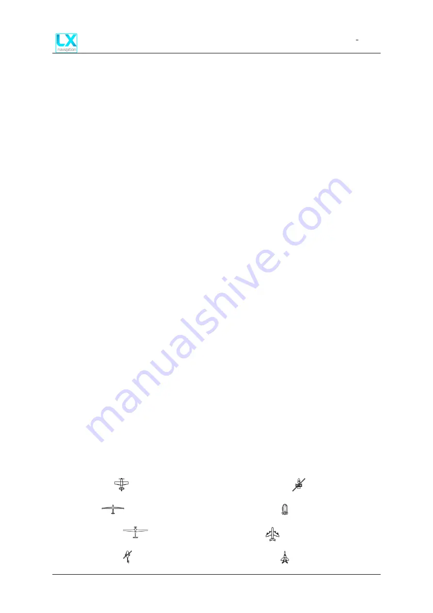
6.5 Aircraft icon

Aircraft is displayed at the bottom of the page with icon. To change the aircraft icon, go to
setup, system section and select “Aircraft”.

Go to “Category” and select from the list:

Airplane -

Glider -

Motor glider -

Rotorcraft -

Gyrocopter -

Airship -

Jet -

Fighter -

Device manual

Public

29

Summary of Contents for iris EFIS

Page 1: ...iris EFIS User manual ...

Page 2: ...LX iris EFIS 57 80 Device manual LX navigation May 2020 Tkalska ulica 10 SI 3000 Celje Tel 00 386 3 490 46 70 Fax 00 386 3 490 46 71 info lxnavigation com www lxnavigation com ...

Page 3: ...LX iris EFIS The installation manual data port and additional info can be found on www lxnavigation com 0 2 List of applicable products Device Version LX iris EFIS 57 V1 0 LX iris EFIS 80 V1 0 0 3 Revision history Document Document SW Revised Approved name revision version Date by by Notes LX HUM R1 1 0 13 5 2020 L A N S Manual written Device manual Public 3 ...

Page 4: ...rade iris EFIS to iris EIFS pro 10 2 1 2 iris EFIS pro 10 2 2 Licenses 10 3 Basic operation 11 3 1 Push rotary knobs and buttons 11 3 1 1 Overview 11 3 2 Switching the unit on 11 3 3 Switching the unit off 12 3 4 Alphanumeric inputs 12 3 5 Software update procedure 12 3 6 File transfer 13 4 User interface 14 4 1 Pages 14 4 1 1 Pages overview 14 5 PFD page 15 5 1 Attitude indicator 16 5 1 1 Attitud...

Page 5: ...12 3 Pitch attitude offset 27 6 APT navigation page 28 6 1 Overview 28 6 2 Wind widget 28 6 3 Wind calculation 28 6 4 Zoom level 29 6 4 1 Map scale bar 29 6 4 2 Zoom level appearance 29 6 4 3 Zoom level marked with Map scale bar 0 2 0 5 1 3 5 9 29 6 4 4 Zoom level marked with Map scale bar 12 25 50 125 29 6 5 Aircraft icon 29 6 6 Navigation lines 30 6 7 NavBox line 31 6 7 1 NavBox 31 6 7 2 Navbox ...

Page 6: ... 7 4 4 Next turnpoint 50 7 7 4 5 Previous turnpoint 50 7 7 4 6 Exit 50 8 G force page 51 8 1 Overview 51 8 2 Graphic G force presentation 52 8 3 Change the G force scale 52 8 4 G force options 52 9 Info page 53 9 1 GPS status 53 9 2 GPS coordinates 53 9 3 UTC time and date 54 9 4 OAT 54 9 5 Density altitude 54 9 6 Current power supply voltage 54 9 7 Battery 54 10 Logbook page 55 10 1 Pilots logboo...

Page 7: ...13 2 4 Warnings 69 13 2 5 Logger 69 13 3 System section 70 13 3 1 Aircraft 70 13 3 2 Units 72 13 3 3 NMEA 72 13 3 4 Transfer 74 13 3 5 Network 75 13 3 6 Localisation 75 13 3 7 Service 76 13 3 8 Shutdown 77 13 3 8 1 Force shutdown 77 14 Taking care of your iris EFIS 78 14 1 The internal battery 78 14 2 Pressure sensors 79 14 3 Display 79 14 4 RJ connectors 79 14 5 MicroSD card reader 79 14 6 Revers...

Page 8: ...rmation is provided for reference only The pilot takes all responsibility and risk associated with the use of this device Have a nice flight 1 3 Limited warranty This device is warranted to be free from defects in materials or workmanship for two years from the date of purchase Within this period LX navigation will at its sole discretion repair or replace any components that fail in normal use Such...

Page 9: ...arranty and will be considered as misuse of the device To learn how to take care of your display and device in whole check the Taking care of your iris EFIS section of this manual 1 5 Disclaimer EULA LX navigation reserves all rights to this document and the information contained herein Products names logos and designs described herein may in whole or in part be sub ject to intellectual property r...

Page 10: ...ive for purchasing the license 2 1 2 iris EFIS pro Is the extended version with PFD page and Setup page and additional navigation pages APT page Airport navigation RTE page Route navigation G Force page Info page Logbook page and Airspace page 2 2 Licenses License file EfisPro lic is generated for your specific device based on device serial number Often referred to as SN License file should be copied ...

Page 11: ...ice Figure 1 Device overview M4X6 black mounting screw 1 Display 2 Left hand button 3 Micro SD card slot 4 Left hand push rotary knob 5 M4X6 black mounting screw 6 Right button 7 Right hand push rotary knob 8 3 2 Switching the unit on To turn the unit on press and hold the left push rotary knob for 3 seconds Marked with the power symbol Device manual Public 11 ...

Page 12: ... scroll through the list and press the push rotary to confirm the symbol and continue typing the next symbol Once finished find the Enter icon to confirm your input Figure 2 Keyboard for alphanumeric input 3 5 Software update procedure To update your device copy the SW version to the root of provided Micro SD card Insert it into the slot on the front panel Use left or right button to move through page...

Page 13: ...el Use left or right button to move through pages Go to setup page In the section System go to Transfer menu Use right hand push rotary knob to select Turnpoints Airports Airspace or Load route Once the pilot selects which type of file to upload a new menu appears Select Load to download the selected file from the list To activate the loaded file go to Select and select the file from the list Device m...

Page 14: ...ge Page Short position name description 1 PFD page Attitude indicator with Airspeed and Altitude tape 2 APT navigation page Navigational page to a pilot selected airport 3 RTE navigation page Navigational page to a pilot defined route 4 G force page G force page with minimal maximal and actual G load 5 Info page Info page with GPS time date and battery status 6 Logbook page Pilots digital logbook w...

Page 15: ... 4 Land Representation 5 Sky Representation 6 Pitch Scale 7 Roll Scale Zero 8 Heading True track bug setting 9 Heading True track bug 10 Current magnetic heading 11 90 degree left turn 12 90 degree right turn 13 Vertical speed indicator 14 Altitude tape BARO 15 Current altitude 16 Airspeed indicator 17 Current airspeed 18 Ground speed GS 19 Current airspeed 20 Device manual Public 15 ...

Page 16: ...ll and slip skid information 5 1 3 Pitch The horizon line is part of the pitch scale Pilot can see following pitch scale markings 0 pitch markings Known also as Horizon line 2 5 pitch markings Found at the interval between 0 and 20 5 pitch markings Found at the interval of 50 10 pitch markings Found at the interval between 50 and 90 5 1 4 Roll and roll scale The inverted white triangle indicates z...

Page 17: ... airspeed is disabled Show altitude is enabled 5 2 1 Overview The indicated airspeed tape displays 30 km h 30 kts 30 mph values at a time on a rolling number gauge using a moving tape Numeric labels with white mark are shown at intervals of 10 km h 10 kts 10 mph Minor airspeed marks white lines are shown at intervals of 5 km h 5 kts 5 mph The current indicated airspeed is displayed in the black po...

Page 18: ... a problem with GPS 5 2 3 Disabling the indicated airspeed tape In the setup page go to user section Graphic and select menu AHRS Go to Show airspeed Pilot can chose between on and off Figure 8 Show airspeed Show altitude Show direction options in setup page graphic AHRS menu Figure 9 Show airspeed is disabled Show altitude is disable and Show direction is set to True Track Device manual Public 18...

Page 19: ... gauge using a moving tape Numeric labels and major altitude marks white lines are shown at intervals of 100 feet Minor altitude marks white lines are shown at inter vals of 50 feet The current altitude is displayed in the black pointer box with a big value Disabling the altitude tape In the setup page go to user section Graphic and select menu AHRS Go to Show airspeed Pilot can chose between on a...

Page 20: ...n the PFD page turn the right hand push rotary knob Selection Knob to change the barometric pressure Turn it clockwise to set higher barometric pressure or counter clockwise to set lower barometric pressure Figure 16 BARO settings indicator The Altitude Alerting function provides the pilot with a visual alert when approaching the Se lected Altitude Whenever the Selected Altitude is changed the Alt...

Page 21: ...dden when TAS is less than 36 km h The pilot performs standard rate turn when roll indicator marker yellow triangle aligns with airplane silhouette Although standard rate turn is defined as 3 per second turn which gives a complete 360 turn in 2 minutes device allows pilot to select whether 2 minute or 1 minute turn is indicated by standard rate turn indicator 5 5 3 Standard rate turn indicator sett...

Page 22: ...ith the raster of 0 5 Figure 20 Direction tape with Bug function Major marks taller white lines are shown at intervals of every 10 Minor marks shorter white lines are shown at intervals of every 5 The current magnetic heading is displayed in the black pointer box with a big value In the left corner pilot can see the white pointer and value which indicates 90 left turn and its magnetic heading valu...

Page 23: ...ction tape bug options show direction Figure 22 Direction tape bug Show direction options In the setup menu pilot must go to user section select graphic and then AHRS Scroll down to Show direction and press to select Pilot can select between Magnetic heading True track and Off If Magnetic heading option is selected the bug will be set to pilot selected magnetic heading If True track option is sele...

Page 24: ... next TP turnpoint from the preadjusted RTE route navigation page or selected APT airport at the APT navigation page whichever was changed selected later If APT mode is selected LX horizon will automatically select heading to the APT airport selected at the APT navigation page If RTE mode is selected LX horizon will automatically select heading to the next point APT or TP selected at the RTE navig...

Page 25: ...et and Brightness At the top of the display pilot can see the GPS status icon and Battery status icon Figure 24 Quick settings menu 5 12 1 GPS status At the top of Quick settings menu pilot can quickly access to GPS indication icon GPS icon will be green if LX horizon has a valid GPS signal and red if LX horizon doesn t have a valid GPS signal Figure 25 GPS signal is not valid Figure 26 GPS signal...

Page 26: ...onomy Main battery indicator Battery outline is white 3 green bars more than 12 0V 2 yellow bars more than 10 8V 1 red bar less than 10 8V Figure 27 3 green bars more than 12 0V Figure 28 2 yellow bars more than 10 8V Figure 29 1 red bar less than 10 8V Backup battery indicator Battery outline is red 3 green bars 81 100 backup battery left 2 yellow bars 21 80 backup battery left 1 red bar less tha...

Page 27: ...e right hand push rotary knob while on PFD page Rotate the push rotary knob to a desired value Press to confirm If not in 5 seconds the device will automatically exit the menu and the selected pitch attitude offset will be confirmed NOTE Access the pitch attitude offset by short or long press of a right hand push rotary knob while on PFD page Rotate to move 20 and press in to confirm Device manual Pu...

Page 28: ...et Wind widget can be found in the lower left corner of the display On the black background pilot can see Wind direction in degrees relative to aircraft heading Black arrow on the green circle Wind direction in degrees with a wind socket icon Wind speed with units below Wind direction in degrees 6 3 Wind calculation LX horizon is able to measure wind using an iterative method that is based on indi...

Page 29: ...h Map scale bar 0 2 0 5 1 3 5 9 3D terrain map is displayed with airspace and airports marked with APT icon and name of airport Edit graphic settings in setup page user section Graphic and enter the Map Edit airspace appearance in setup page user section Graphic and enter the Airspace 6 4 4 Zoom level marked with Map scale bar 12 25 50 125 3D terrain map is not displayed Black background appears w...

Page 30: ...Both are user defined in the setup menu user section graphic and select Destination line or Track line color Figure 36 Track line color select Figure 37 Destination line color se lect Circular color menu will appear Rotate the right hand push rotary knob to select the color and confirm by pressing in After confirming the transparency setting will appear with same circular menu Rotate the right hand p...

Page 31: ... NavBox NavBox is the single information that is displayed by LX device as title and value with unit Figure 39 One NavBox item 6 7 2 Navbox line setup To move through NavBox lines use right hand push rotary knob and rotate it As pilot moves through NavBox lines one can see the indicator number changes The movement through NavBox lines is circular LX horizon supports 3 NavBox lines and additional d...

Page 32: ...ress in to select which one to edit Figure 40 Press and hold the right hand push rotary knob to edit NavBox Once pilot has selected the NavBox he wants to edit a drop down menu will appear with all available NavBox information UTC time Local time Flight time Leg time Total distance Remaining distance ETE Estimated Time Enroute ETA UTC ETA local time Leg distance Leg ETE Leg ETA UTC Leg ETA local A...

Page 33: ...ach NavBox information available Press the push rotary knob to select the NavBox information 6 8 Select APT Figure 42 Select Navbox menu On the APT page pilot can navigate to selected airport To select the airport press the right hand push rotary knob while at APT page A Select airport menu will appear First row is the search parameters Device manual Public 33 ...

Page 34: ...he distance From the closest to the furthest airport Name which will sort the results based on the name in the alphabetical order Once pilot have selected the desired Sort by parameter by pressing the right hand push rotary knob one can can apply next parameter which is Filter On the left side of the display a circular motion keyboard will appear Use right hand push rotary knob to rotate and searc...

Page 35: ...an apply next parameter which is Country Default value is All which will search all available countries Use right hand push rotary knob to rotate and move through circular list of countries sorted by alphabetical order To move through the list faster by 10 lines at the rotate press in right hand push rotary knob and rotate while pressed Figure 45 Adding Country parameter with rotating right hand p...

Page 36: ... 46 Scroll down and select the desired APT Rotating bearing icon to the selected airport Relative bearing relative to track Distance to the selected airport Bearing to the selected airport in degrees Absolute bearing relative to true north The selected airport can be confirmed by press of the right hand push rotary knob Once the airport is selected device will return to APT navigation page Figure 4...

Page 37: ...ppear If some data is not available No data text will appear under the title of information Figure 48 Selected APT details The list of displayed data if available in the APT file Rotating bearing icon to the selected airport Relative bearing relative to track and Bear ing to the selected airport in degrees Absolute bearing relative to true north Distance to the selected airport Radio frequency of t...

Page 38: ...t can be found in the lower left corner of the display On the black background pilot can see Wind direction in degrees relative to aircraft heading Black arrow on the green circle Wind direction in degrees with a wind socket icon Wind speed with units below Wind direction in degrees 7 2 Wind calculation LX horizon is able to measure wind using an iterative method that is based on indicated airspee...

Page 39: ...h Map scale bar 0 2 0 5 1 3 5 9 3D terrain map is displayed with airspace and airports marked with APT icon and name of airport Edit graphic settings in setup page user section Graphic and enter the Map Edit airspace appearance in setup page user section Graphic and enter the Airspace 7 3 4 Zoom level marked with Map scale bar 12 25 50 125 3D terrain map is not displayed Black background appears w...

Page 40: ...Both are user defined in the setup menu user section graphic and select Destination line or Track line color Figure 51 Track line color select Figure 52 Destination line color se lect Circular color menu will appear Rotate the right hand push rotary knob to select the color and confirm by pressing in After confirming the transparency setting will appear with same circular menu Rotate the right hand p...

Page 41: ...d rotate it As pilot moves through NavBox lines one can see the indicator number changes The movement through NavBox lines is circular LX horizon supports 3 NavBox lines and additional disabled mode which hides the NavBox line and extends the map 7 6 3 Edit NavBox NavBoxes will appear on the APT and RTE navigation pages All NavBoxes are pilot defined To change the NavBox press and hold right hand p...

Page 42: ...ETA local Altitude Flight level Density altitude Height AGL Elevation Vertical speed Ground speed True track Magnetic heading Bearing OAT G force Flap position Figure 55 Navbox select menu Rotate the right hand push rotary knob to move through each NavBox information available Press the push rotary knob to select the NavBox information 7 7 Edit route On the RTE page pilot can navigate to according...

Page 43: ...must press the right hand push rotary knob to select the T take off point Figure 57 Selecting T take off or L landing will take pilot to Select action menu Select action menu will appear At this point pilot will have to decide to start his route either with turnpoint or airport If he decides to start with turnpoint rotate and press to select Select turnpoint A menu Select turnpoint appears Device ...

Page 44: ...right hand push rotary knob one can can apply next parameter which is Filter On the left side of the display a circular motion keyboard will appear Use right hand push rotary knob to rotate and search for each letter Once the letter is selected press right hand push rotary knob to select it Use it to add 0 12 signs to use as Filter parameter Once pilot have selected the desired Filter parameter by...

Page 45: ...ance to the selected airport Bearing to the selected airport in degrees The selected turnpoint can be confirmed by press of the right hand push rotary knob Once the turnpoint is selected device will return to Edit route menu Selected turnpoint will be displayed as a Take off point T 7 7 1 2 Select airport If the pilot decides to start the route with airport one should rotate and press to select Sel...

Page 46: ...which is Filter On the left side of the display a circular motion keyboard will appear Use right hand push rotary knob to rotate and search for each letter Once the letter is selected press right hand push rotary knob to select it Use it to add 0 12 signs to use as Filter parameter Once pilot have selected the desired Filter parameter by pressing the right hand push rotary knob one can apply next ...

Page 47: ...on to the selected airport Distance to the selected airport Bearing to the selected airport in degrees The selected airport can be confirmed by press of the right hand push rotary knob Once the airport is selected device will return to Edit route menu Selected airport will be displayed as a Take off Device manual Public 47 ...

Page 48: ...ert a new turnpoint or airport into pilots route one should select the L Landing point and press of the right hand push rotary knob A Select action menu will appear with new options Figure 63 Select action menu Pilot should select either Insert turnpoint or Insert airport to insert additional point into de sired route Device manual Public 48 ...

Page 49: ...and press to select the point you want to delete A Select action menu will appear with the option Delete 7 7 4 Route options Figure 64 route options menu accessible push left hand pus rotary knob while at RTE page To access Route options menu press the left hand push rotary knob while at RTE navigation page 7 7 4 1 Edit route Refer to menu Edit route 7 7 4 2 Delete route Select the option to quick...

Page 50: ... Quickly select next turnpoint in your planned route Disabled grey text if your current position is Landing 7 7 4 5 Previous turnpoint Quickly select previous turnpoint in your planned route Disabled grey text if your current position is Take off 7 7 4 6 Exit Exit this menu Device manual Public 50 ...

Page 51: ...an see the MIN which is minimal G force reached in the current flight On the right side pilot can see the MAX which is maximal G force reached in the current flight On the left side of the display pilot can see the Airspeed tape To find out more refer to Airspeed tape section of the manual Below is the TAS True airspeed information On the right side of the display pilot can see the Altitude tape To fi...

Page 52: ... load is also displayed as red dot on the G force scale 8 3 Change the G force scale To change the G force scale rotate the left hand push rotary knob Pilot can select between 1G to 9G scale depending on the precision and load he expects to reach 8 4 G force options Figure 66 G force options Press right hand push rotary knob to enter G force options Pilot can select Reset option which will reset t...

Page 53: ...S source Check if the antenna is connected properly Check if antenna is working Once the device will receive the valid GPS source the status will change to 3D 4 3D 5 3D 6 3D 7 3D 8 3D 9 3D 10 3D 11 3D 12 etc Any GPS status above 3D 7 is considered as a strong GPS signal 9 2 GPS coordinates If the device has a valid GPS source the current GPS coordinates will be displayed in the left sec tion below...

Page 54: ...ying 9 6 Current power supply voltage Current voltage will be displayed The unit is Volt V Pilot must be careful if the voltage drops below 9V or is higher than 32V 9 7 Battery Actual backup battery voltage is displayed as Battery Pilot must be careful if the voltage drops below 3V or is higher than 5V Backup battery is automatically charged all the time it is powered on and will automatically swi...

Page 55: ... of thousands of flight hours Last 50 flight will be displayed as date of flight duration of flight and pilot name below All the flights are filtered by the date added Use right hand push rotary knob to scroll through the list To select press the push rotary knob 10 2 Flight details By pressing the hand rotary knob selecting the specific flight pilot will enter the flight details page Displaying the name t...

Page 56: ...ransfer Select Transfer to SD to download your flight to Micro SD card inserted in the slot between the buttons on the front of the device The Transfer pop up message should appear If the transfer is not successful check if the SD card has been inserted correctly Please use only manufacturer provided Micro SD card Figure 70 Info page Device manual Public 56 ...

Page 57: ...UM Document revision R1 NOTE Always use manufacturer provided Micro SD card Third party SD cards might not function with this device In case the card is lost contact your local official representative or LX navigation d o o Device manual Public 57 ...

Page 58: ...e Device is in flight mode if it has a valid Airspeed and Altitude input 11 2 Statistics information Statistics information displays the barograph curve with time on the x axis and altitude on the y axis Altitude scale will adjust according to the highest altitude achieved in a specific flight Additional line of 4 different parameters can be found at the bottom of the page Takeoff Take off time UTC D...

Page 59: ... manually end flight press right hand push rotary knob while on statistics page A pop up message will appear Select yes or no with the same push rotary knob Figure 73 Device will end flight automatically after the airspeed and altitude is 0 Device will automatically finish the flight and begin with the countdown of 15 seconds after the Airspeed and Altitude is 0 Device manual Public 59 ...

Page 60: ...l the near and active airspace To transfer the airspace file as go to Setup System section and Transfer menu 12 1 List of airspace At the list of airspace pilot can see the name of the airspace and its class below On the right is relative distance On the right part of the line are the vertical limits in meters feet of altitude height AGL or flight level FL Device manual Public 60 ...

Page 61: ...12 2 Airspace details By pressing right hand push rotary knob on selected airspace from the list pilot will access Airspace details page Device will display a graphical representation of the airspace and the current aircraft position along with the information already available on previous page Figure 77 Airspace details page with graphical representation of airspace Device manual Public 61 ...

Page 62: ... settings are concerning the pilot s personal preferences and setting which will change if the pilot selects of the pilot profile while System settings are concerned to the device setup and stay fixed all the time 13 2 User section User section of setup are settings of the pilot which will change if the active pilot will change User section setup items are Pilot Pages Graphic Warnings Logger Device ...

Page 63: ...t Figure 78 Setup page and Pilot menu Pilot settings will allow the pilot to Select active pilot Select from the list Write a name of the pilot Write a surname of the pilot Enable disable club profile Password Import pilot file Export pilot file Delete pilot Device manual Public 63 ...

Page 64: ...ge RTE page G force GPS Info Logbook Airspace Figure 79 Pages menu With a right hand push rotary knob we can move though menu and press to select each item Once the item is selected the indication icon will change Default page Default page setting allows the pilot to select the default page of the device the first page the pilot will see when the device will power on Device manual Public 64 ...

Page 65: ...ge RTE page G force page PFD page Info page Logbook page Airspace page Default setting is AHRS page 13 2 3 Graphic Graphic menu will allow the pilot to set the visual parameters of the device Graphic menu contains Airspace Visual settings Map Visual settings Route Visual settings AHRS Visual settings Theme Visual settings Device manual Public 65 ...

Page 66: ...e color Class A B Set Outline and Fill color Class C Set Outline color Class D Set Outline color Class E Set Outline color Class F Set Outline color 13 2 3 2 Map In the Map menu pilot can adjust various map related settings Orientation Select between Track up and North up Color Palette Select between 14 different 3D terrain relief color palettes TP APT text size Select between Small Normal and Lar...

Page 67: ...olor Palette Imhof 1 Figure 84 Color Palette Imhof 2 Figure 85 Color Palette Imhof 3 Figure 86 Color Palette LX Navigation 3 Figure 87 Color Palette LX Navigation 4 Figure 88 Color Palette ICAO Figure 89 Color Palette Orange Figure 90 Color Palette UK Figure 91 Color Palette Black and white Figure 92 Color Palette Black no elevation Device manual Public 67 ...

Page 68: ...ourse to next TP Set the color and transparency level Covered leg Set the color and transparency level 13 2 3 4 PFD In the PFD menu pilot can adjust specific elements on the PFD page Show airspeed On or Off option Show altitude On or Off option Show direction Select between Magnetic Heading True Track and Off Sync HDG bug Select between Auto APT RTE and None Turn coordinator Select between 1 min 2 ...

Page 69: ...at Setup page System section Aircraft menu Airspeed menu Stall On or Off option Vne On or Off option 13 2 5 Logger In the Logger menu pilot can adjust various logger related parameters Figure 94 Logger settings Interval Set logger interval value 0 15 s Event interval Is fixed at 1 s Event fixes Select value between 30 60 Start speed Select value between 18 151 km h Device manual Public 69 ...

Page 70: ...lisation Service Shutdown 13 3 1 Aircraft Airspeed Insert value for Vs1 Vn0 and Vne Registration nr Insert aircraft registration number Category Select aircraft category Figure 95 Aircraft menu In the Aircraft menu pilot can access the 3 different aircraft related settings Airspeed Set the Vs1 Vs0 Vne for Airspeed tape link this Registration nr Set aircraft registration number Category Select airc...

Page 71: ...FIS Setup page Document name LX HUM Document revision R1 Figure 96 Aircraft menu Airspeed section Figure 97 Aircraft menu Category section Figure 98 Aircraft menu Registra tion nr section Device manual Public 71 ...

Page 72: ... or m s Distance Select km nm or mI Pressure Select hPa or inHg Temperature Select C or F Weight Select kg or lb Area Select m2 or ft2 Figure 99 Setup page Units section 13 3 3 NMEA In the NMEA section pilot can adjust all communication protocols between LX navigation device and third party peripherals To find out more please refer to LX NMEA 1 0 Protocol and LX NMEA 2 0 Protocol document Flarm Sel...

Page 73: ...0 flight data LXWP1 device info LXWP2 basic parameters LXWP3 detailed parameters sentences LXDT On or Off option LX device enables LXDT communication input and output On or Off option LX device outputs LXBC sentences AHRS data etc LXBC On or Off option LX device outputs LXBC sentences AHRS data etc When Radio option is enabled On all other outputs on User port are disabled but are still present via...

Page 74: ...Route files cup For Task and Route files af For Airport file NOTE Pilot must be careful to not exceed the maximal upload file size of 750 kb Database webpage http www lxnavigation com support database Turnpoints Load Delete Select or Deselect Airports Load Delete Select or Deselect Airspace Load Delete Select or Deselect Load route Load Delete Select or Deselect Figure 101 Setup page Transfer section ...

Page 75: ...luetooth server Bluetooth client WiFi Access point or WiFi client Wireless setup Enter BT Server with Name and Password Figure 102 Setup page Network section Wireless section of Cloud menu Mail Enter Mail with Add mail option 13 3 6 Localisation In the Localisation section pilot can adjust Language and Timezone Language Select English or Slovene option Timezone Select timezone from the list DST Da...

Page 76: ... Club mode Must be enabled first with Password Club mode is special operation mode which disables pilot to erase and change any settings on the device Cage AHRS Set your current AHRS position as horizontal position pitch 0 roll 0 Uncage AHRS Reset your offsets made by Cage function to actual values Software update Select the version from the list For procedure go to section Software update procedur...

Page 77: ...f the Setup menu Select the Shutdown option A pop up message will appear use the right hand push rotary knob to select Yes if you are positive to shutdown the device or No if not Figure 104 Setup page Shutdown at the bottom of the page 13 3 8 1 Force shutdown Force shutdown the device by pressing the left hand push rotary knob for 15 seconds Device manual Public 77 ...

Page 78: ...he internal battery Draining the battery completely is a known culprit for reducing battery capacity If you see the iris EFIS changed to its internal power supply think about heading to your home airfield Proper winter storage During periods of long inactivity especially during winter when cold temperatures are present the battery capacity is lowered by cold temperatures and it can easily happen th...

Page 79: ... your cockpit as well as the display of the iris EFIS Applying excessive heat will make the coating of the display start to become yellow and bubble best case scenario or destroy the device completely This is why it is prudent to always have your canopy covered from direct sunlight 14 4 RJ connectors RJ connectors RJ12 and RJ45 on the back of the iris EFIS are used for connecting external devices ...

Page 80: ... navigation d o o Tkalska ulica 10 SI 3000 Celje Slovenia VAT ID Company is registered in Slovenia EU under the VAT ID SI40539601 Webpage www lxnavigation com Phone 386 0 3 490 46 70 Fax 386 0 3 490 46 71 Sales sales lxnavigation com Support info lxnavigation com Device manual Public 80 ...

Page 81: ...___________________________________________ Warranty repair form Invoice number Mandatory attaching the copy of original invoice ___________________________________ Signature ___________________________________ The repair system works on principle of first come first served The unit will be added to an internal repair system and inspected Aſter inspection the customer will receive the informational e...

Page 82: ......

Reviews: