


035-18200-000-B-1102
Unitary Products Group
13
After the supply air blower motor is operating, adjust
the resistances in both the supply and the return duct
system to balance the air distribution throughout the
conditioned space. The job specification may require
that this balancing be done by someone other than the
equipment installer.
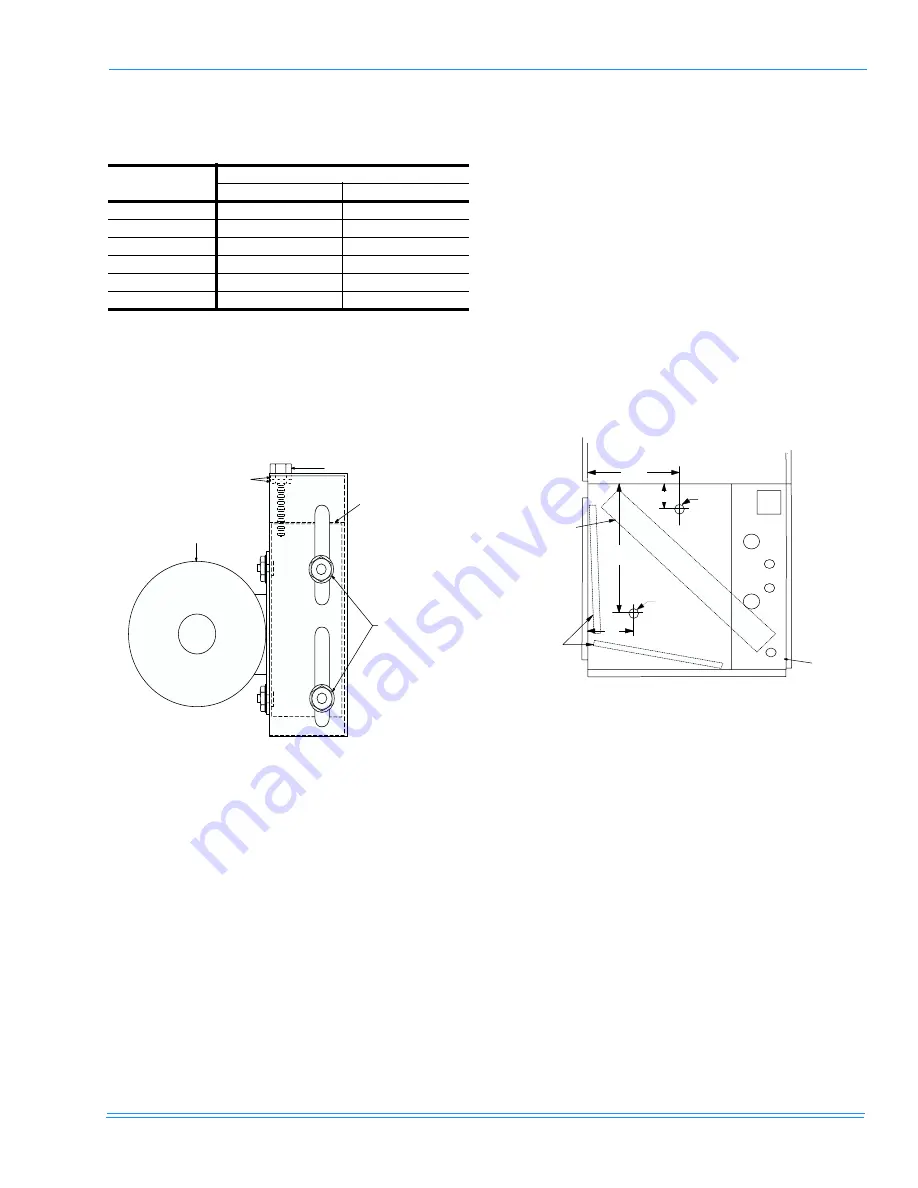
To check the supply air CFM after the initial balancing
has completed”
1.
Drill two 5/16” holes in the side panel as shown in
Figure 15.
2.
Insert at lest 6” of 1/4” tubing into each of these
holes for sufficient penetration into the air flow on
both sides of the indoor coil.
NOTE:
The tubes must be inserted and held in a posi-
tion perpendicular to the air flow so that veloc-
ity pressure will not affect the static pressure
reading.
3.
Using an inclined manometer, determine the pres-
sure drop across a dry indoor coil. Since moisture
on the coil may vary greatly, measuring the pres-
sure drop across a wet coil under field conditions
would be inaccurate. To assure a dry coil, the heat
pump system should be de-activated while the test
is being run.
4.
Knowing the pressure drop across a dry coil the
actual CFM through the unit can be determined
from the curve in Fig. 16.
If the CFM is above or below the specified value, the
supply air motor pulley may have to be re-adjusted.
After one hour of operation, check the belt and pulleys
for tightness and alignment.
After readings have been obtained remove the tubes
and seal up the drilled holes in the side panel. Dot
plugs (5/16” - P/N 029-13880-000) are available
through Source One Parts ordering procedures.
NOTE:
Shut down the heat pump system before tak-
ing any test measurements to assure a dry
indoor coil.
TABLE 6: SUPPLY AIR BLOWER MOTOR PULLEY
ADJUSTMENT
TURNS
OPEN
DRIVE RANGE
625-810 RPM
827-986 RPM
5
625
827
4
662
859
3
699
891
2
736
923
1
773
955
0
810
986
FIGURE 14: TYPICAL MOTOR MOUNTING
ASSEMBLY
B
A
(DO NOT LOOSEN)
MOTOR
MOTOR MOUNT
C
FIGURE 15: HOLE LOCATIONS FOR PRESSURE
DROP READINGS
5 / 1 6 "
H O L E
5 / 1 6 "
H O L E
1 8 "
7 "
2 2 "
1 0 "
E V A P O R A T O R
C O I L
F I L T E R S
C O I L S E C T I O N