Redundant I/O Modules
▪
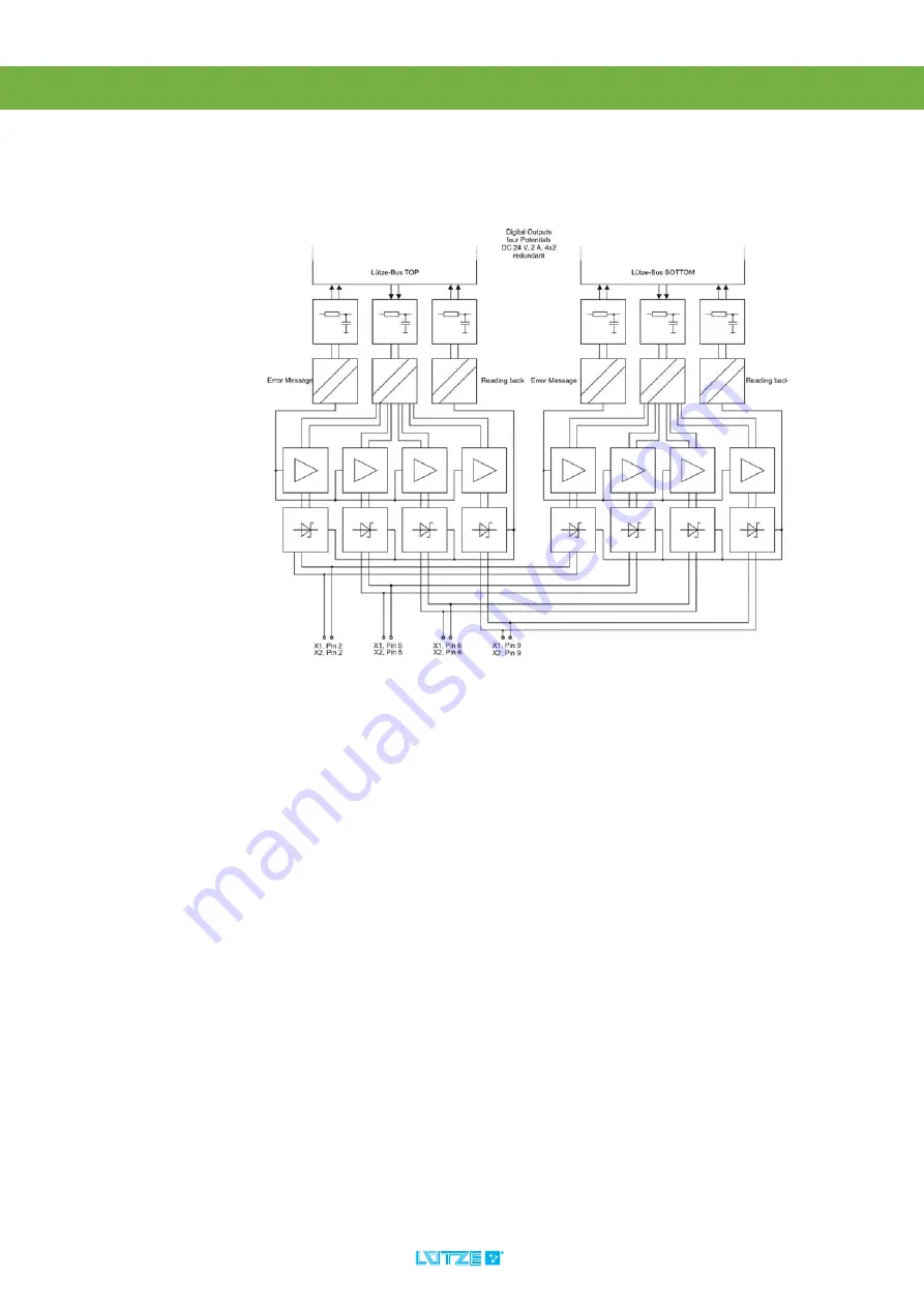
Digital Outputs
59
11.4.6
Operation
11.4.6.1
Block Diagram 8 Digital Outputs 24 V, 4 Potentials
Page 1: ...Operating Instructions DIOLINE 20 Redundant I O Modules Version 1 10...
Page 2: ...L tze Transportation GmbH Bruckwiesenstra e 17 19 D 71384 Weinstadt Tel 49 0 7151 6053 545 Fax 49 0 7151 6053 6545 Sales Transportation luetze de www luetze transportation de...
Page 3: ...ing 13 6 Scope of Delivery 14 7 General Technical Data 15 8 Mounting 17 8 1 Mounting Options 18 9 Initial Operation Hardware 19 9 1 Power Supply 19 9 2 L Bus Interface 20 9 2 1 Connecting One Channel...
Page 4: ...24 V 4 Potentials 53 11 4 1 Product Assembly 53 11 4 2 LED Display 54 11 4 3 Technical Data 55 11 4 4 Connecting the Digital Outputs 56 11 4 5 Diagnosis 58 11 4 6 Operation 59 12 Digital Combination...
Page 5: ...t I O Modules It contains important information about the handling and safety To avoid hazardous situations read the manual before installing the product and using it Store the manual at a handy place...
Page 6: ...by titleholder 2 3 Disclaim of Liability The manual was written under consideration of the applied standards regulations and the current state of technology The content is verified of accuracy Discre...
Page 7: ...ndant I O Modules General Information 7 2 4 Related Documents The redundant modules are always operated with different PLCs or buscoupler Read the manual of the PLC or buscoupler before using the modu...
Page 8: ...s different qualification levels are differentiated 3 3 1 Operating Employees Trained Employees The employee was trained by the employer on the task and possible hazardous situations The employee does...
Page 9: ...arts of the buscoupler which can cause a malfunction of the whole product Follow the instructions and regulations of the employer Reconstructions and modifications of the product can cause property da...
Page 10: ...able as Description Item Number 16 DI DC 24 V 2 Potentials redundant 746430 16 DI DC 24 V 4 Potentials redundant 746431 16 DO DC 24 V 1 A 2 Potentials redundant 746432 8 DI 8 DO DC 24 V 1 A 2 Potentia...
Page 11: ...max 10 local redundant modules to the controller The extension modules are connected via the L Bus The graphic shows the DIOLINE product after their intelligence The first module is the most intellige...
Page 12: ...Redundant I O Modules Product Overview 12 4 3 Field of Application The DIOLINE20 Redundant I O Modules can be connected to buscoupler or PLCs...
Page 13: ...the product in a dry room between 40 and 85 C Make sure that the modules are safely packaged for transporting to absorbe possible crushes Dust can destroy electronic components The circuit boards of t...
Page 14: ...Redundant I O Modules Scope of Delivery 14 6 Scope of Delivery DIOLINE20 redundant Module Plug in Connector Instruction Leaflet...
Page 15: ...aluminum Mounting top hat rail Electronic Module Supply Voltage Supply DC 16 8 30 V Ripple max 10 150 mm 0 5 302 mm TS35 TS35 84 mm 57 mm 45 mm 64 mm 3 mm R Technik mit System DIOLINE 20 redundant DO...
Page 16: ...0 min according to EN 50155 class TX Storage Temperature range min max 40 C bis 85 C Standards EN 50155 Electronic equipment on railway vehicles EN 50121 Electromagnetic compability EN 50124 Insulatio...
Page 17: ...s mandatory Mount the module with following distances Top 10 mm Bottom 30 mm Right to the next redundant module 0 mm Right to the next one channel module 8 10 mm Mount an end bracket 1 between these m...
Page 18: ...Redundant I O Modules Mounting 18 8 1 Mounting Options The redundant module is going to be mounted on a top hat rail Following mounting options are possible horizontal vertical across...
Page 19: ...find information about the pin assignments 9 1 Power Supply The built in microcontroller of the digital Redundant I O Modules is feeded by the L Bus interface The power supply has to be connected ove...
Page 20: ...max 10 redundant modules over the L Bus interface Mind the current consumption of the single modules In the appendix on page 70 the according values are listed A total current of max 1 A is possible o...
Page 21: ...scoupler with I O Modules If connecting one channel modules to the redundant modules the ribbon cable can be stressed For protection it is possible to place a braided wire sleeving around the ribbon c...
Page 22: ...the inputs and the system bus And also between the inputs of the different groups Antiparallel Diode Avoids the damage of entry levels at the confusing of poles of the input and the ground Suppressor...
Page 23: ...ce outgoing 2 LED Diagnosis Display Inputs 1 3 L Bus Interface outgoing 4 LED Diagnosis Display Inputs 2 5 Connector Digital Inputs 6 Connector Digital Inputs 7 Neutral Conductor Mounting Tab 8 L Bus...
Page 24: ...10 2 2 LED Display 10 2 2 1 LEDs L Bus 10 2 2 2 LEDs Input Signals LED Color Status LB1A green active LB1ERR red Error LB2A green active LB2ERR red Error LED Color Status Input 1 1 16 orange Sensor a...
Page 25: ...not inverted 0 Signal DC 0 6 V 1 Signal DC 12 5 30 V Input current bottom not inverted 0 Signal 0 mA 1 Signal at DC 24 V min 50 mA for 7 ms when switching on dropping to min 8 mA 1 Signal Threshold m...
Page 26: ...the inputs regarding the pin assignment and the signals Digitale Inputs 24 V 2 Potentials Coding Cage Clamp X1 Pin Signal Description 1 GNDA 0 V Potential A 2 DI1 Input 1 1st Byte LSB 3 DI 2 Input 2 4...
Page 27: ...al Description 1 GNDA 0 V Potential A 2 DI 5 Input 5 3 DI 6 Input 6 4 DI 7 Input 7 5 DI 8 Input 8 1st Byte MSB 6 DI13 Input 13 7 DI14 Input 14 8 DI15 Input 15 9 DI16 Input 16 2nd Byte MSB 10 GNDB 0 V...
Page 28: ...Redundant I O Modules Digital Inputs 28 10 2 5 Operation 10 2 5 1 Block Diagram 16 Digital Inputs 24 V 2 Potentials...
Page 29: ...Bus Interface outgoing 2 LED Diagnosis Display Inputs 1 3 L Bus Interface outgoing 4 LED Diagnosis Display Inputs 2 5 Connector Digital Inputs 6 Connector Digital Inputs 7 Neutral Conductor Mounting T...
Page 30: ...10 3 2 LED Display 10 3 2 1 LEDs L Bus 10 3 2 2 LEDs Input Signals LED Color Status LB1A green active LB1ERR red Error LB2A green active LB2ERR red Error LED Color Status Input 1 1 16 orange Sensor a...
Page 31: ...d against polarity reversal Signal characteristic curve bottom not inverted 0 Signal DC 0 6 V 1 Signal DC 12 5 30 V Input current bottom bottom not inverted 0 Signal 0 mA 1 Signal at DC 24 V min 50 mA...
Page 32: ...Redundant I O Modules Digital Inputs 32 Transmission frequenzy thermic 10 Hz at 50 ED Module Status Flag The module status flag remains 0 0 no hardware error...
Page 33: ...ts and electronics AC 1 5 kV input potentials against each other Input voltage DC 0 30 V short time protected against polarity reversal Signal characteristics curve 0 Signal DC 0 6 V 1 Signal DC 12 5...
Page 34: ...versal Signal characteristic curve bottom not inverted 0 Signal DC 0 18 V 1 Signal DC 36 90 V Input current bottom not inverted 0 Signal 0 mA 1 Signal at DC 72 V min 15 mA for 5 ms when switching on d...
Page 35: ...Redundant I O Modules Digital Inputs 35 Modul Status Flag The module status flag remains 0 0 no hardware error...
Page 36: ...the pin assignment and the signals Digital Inputs 24 and 72 V 4 Potentials Coding Cage Clamp X1 Pin Signal Description 1 GNDA 0 V Potential A 2 DI1 Input 1 1st Byte LSB 3 DI 2 Input 2 4 DI 3 Input 3 5...
Page 37: ...1 GNDB 0 V Potential B 2 DI 5 Input 5 3 DI 6 Input 6 4 DI 7 Input 7 5 DI 8 Input 8 1st Byte MSB 6 DI13 Input13 7 DI14 Input 14 8 DI15 Input 15 9 DI16 Input16 2nd Byte MSB 10 GNDD 0 V Potential D Modul...
Page 38: ...Redundant I O Modules Digital Inputs 38 10 3 5 Operation 10 3 5 1 Block Diagram 4x4 Digital Inputs 24 V...
Page 39: ...Redundant I O Modules Digital Inputs 39 10 3 5 2 Block Diagram 4x4 Digital Inputs 24 V not inverted...
Page 40: ...Redundant I O Modules Digital Inputs 40 10 3 5 3 Block Diagram 4x4 Digital Inputs 72 V...
Page 41: ...er than the typical cycletime Insulation Channel Enables potential separation between the inputs and the system bus And also between the inputs of the different groups Suppressor Diode and Input Varis...
Page 42: ...e outgoing 2 LED Diagnosis Display Outputs 1 3 L Bus Interface outgoing 4 LED Diagnosis Display Outputs 2 5 Connector Digital Outputs 6 Connector Digital Outputs 7 Neutral Conductor Mounting Tab 8 L B...
Page 43: ...11 2 2 2 LEDs Output Signals LED Color Status LB1A green active LB1ERR red Error LB2A green active LB2ERR red Error LED Color Status Output 1 1 16 orange Actor active Output 2 1 16 orange Actor activ...
Page 44: ...Connection Electrical isolation Isolating voltage AC 1 5 kV inputs outputs and electronics AC 1 5 kV potential A to potential B Output voltage DC 16 8 30 V protected against polarity reversal Output c...
Page 45: ...onnect the ouputs regarding the pin assignment and the signals Digital Outputs 24 V 2 Potentials Coding Cage Clamp X1 Pin Signal Description 1 USA DC 24 V 2 DO1 Output 1 1 Byte LSB 3 DO 2 Output 2 4 D...
Page 46: ...Description 1 GNDA 0 V Potential A 2 DO 5 Output 5 3 DO 6 Output 6 4 DO 7 Output 7 5 DO 8 Output 8 1st Byte MSB 6 DO13 Output 13 7 DO14 Output 14 8 DO15 Output 15 9 DO16 Output 16 2nd Byte MSB 10 GNDB...
Page 47: ...Redundant I O Modules Digital Outputs 47 11 2 5 Operation 11 2 5 1 Block Diagram 16 Digital Outputs 24 V 2 Potentials...
Page 48: ...s 2 5 Connector Digital Outputs 6 Connector Digital Outputs 7 Neutral Conductor Mounting Tab 8 L Bus Interface incoming 9 LED Diagnosis Display L Bus 2 bottom 10 L Bus Interface incoming 11 LED Diagno...
Page 49: ...9 11 3 2 LED Display 11 3 2 1 LEDs L Bus 11 3 2 2 LEDs Output Signals LED Color Status LB1A green active LB1ERR red Error LB2A green active LB2ERR red Error LED Color Status Output 1 1 6 orange Actor...
Page 50: ...utputs and electronics AC 1 5 kV potentials against each other Output voltage DC 24 110 V 16 8 137 5 V protected against polarity reversal Output current max 0 5 A per channel Channel Type N MOS FET S...
Page 51: ...regarding the pin assignment and the signals Digital Outputs 24 110 V 3 Potentials Coding Cage Clamp X1 X2 Pin Signal Description 1 USA 110 V DC Potential A 2 DO1 Output 1 3 DO 2 Output 2 4 USB 110 V...
Page 52: ...Redundant I O Modules Digital Outputs 52 11 3 5 Operation 11 3 5 1 Block Diagram 6 Digital Outputs 24 110 V...
Page 53: ...ce outgoing 2 LED Diagnosis Display Outputs 1 3 L Bus Interface outgoing 4 LED Diagnosis Display Outputs 2 5 Connector Digital Inputs 6 Connector Digital Inputs 7 Neutral Conductor Mounting Tab 8 L Bu...
Page 54: ...r Status LB1A green active LB1ERR red Error LB2A green active LB2ERR red Arror LED Color Status Output 1 1 8 orange Actor active Output 2 1 8 orange Actor active USA OVLA green red Voltage on Overload...
Page 55: ...AC 1 5 kV outputs and electronics AC 1 5 kV output potentials against each other Output voltage DC 16 8 30 V polarity reversal protected Output current max 2 A per channel max 3 A per group and max 12...
Page 56: ...ts regarding the pin assignment and the signals Digital Outputs 24 V 4 Potentials Coding Cage Clamp X1 Pin Signal Description 1 USA 24 V DC Potential A 2 DO1 Output 1 1st Byte LSB 3 NC Not Connected 4...
Page 57: ...gnal Description 1 GNDA 0 V Potential A 2 DO2 Output 2 1st Byte LSB 3 NC Not Connected 4 GNDB 0 V Potential B 5 DO4 Output 4 6 DO6 Output 6 7 GNDC 24 V Potential C 8 NC Not Connected 9 DO8 Output 8 10...
Page 58: ...cuit or overtemperature at the output channel DOx Byte 1 Read back Byte Bit 7 Bit 6 Bit 5 Bit 4 Bit 3 Bit 2 Bit 1 Bit 0 0 0 Switching Status actual Output Channel DO 6 Switching Status actual Output C...
Page 59: ...Redundant I O Modules Digital Outputs 59 11 4 6 Operation 11 4 6 1 Block Diagram 8 Digital Outputs 24 V 4 Potentials...
Page 60: ...12 Digital Combination 12 1 Characteristics Module with In and Outputs Same characteristics as the corresponding in and output modules The four inputs and ouputs inside a group have the same potentia...
Page 61: ...outgoing 2 LED Diagnosis Display Outputs Inputs 1 3 L Bus Interface outgoing 4 LED Diagnosis Display Outputs Inputs 2 5 Connector Digita Outputs 6 Connector Digital Inputs 7 Neutral Conductor Mounting...
Page 62: ...Input Signal OutputSignal LED Farbe Status LB1A green active LB1ERR red Error LB2A green active LB2ERR red Error LED Color Status Output 1 2 upper row 1 8 orange Actor active Input 1 2 lower row 1 8 o...
Page 63: ...tential B Module Status Flag In the error condition of the output driver the module status flag is set to 1 Digital Inputs 24 V Module 2 Potentials Input voltage DC 0 30 V short time protecetd against...
Page 64: ...l max 100 mA at DC 30 V making current min 4 mA at DC 16 8 V continuous current Digital Outputs 24 V Module 2 Potentials Output voltage DC 16 8 30 V protected against polarity reversal Output current...
Page 65: ...r 2 Connect the inputs and outputs regarding the pin assignment and the signals Digital Outputs 24 V 2 Potentials Coding Cage Clamp X1 Pin Signal Description 1 USA DC 24 V Potential A 2 DO1 Output 1 L...
Page 66: ...2 Potentials Cage Clamp X2 Pin Signal Description 1 GNDA 0V Potential A 2 DI1 Input 1 LSB 3 DI2 Input 2 4 DI3 Input 3 5 DI4 Input 4 6 DI5 Input 5 7 DI6 Input 6 8 DI7 Input 7 9 DI8 Input 8 MSB 10 GNDB...
Page 67: ...Redundant I O Modules Digital Combination 67 12 2 5 Operation 12 2 5 1 Block Diagram 8 Digital Inputs 8 Digitale Outputs 24 V 2 Potentials...
Page 68: ...68 13 Demounting To demount the module a screwdriver is mandatory 1 Take the screwdriver Stick the screwdriver in the tab Pull the tab 2 Take the module off the lower hat rail 3 Push the modul up and...
Page 69: ...tze Transportation GmbH from the responsibilities of 10 passage 2 ElektroG Take back obligation of the manufacturer and any third party in this content If you have handled the device to a commercial t...
Page 70: ...If you have any further questions regarding the product or our repairing service please contact us L tze Transportation GmbH Bruckwiesenstra e17 19 71384 Weinstadt Tel 49 0 7151 6053 545 Fax 49 0 717...
Page 71: ...dix 16 1 Overview DIOLINE 20 Identifier Type I O Range Length Bytes ID hex I O 16 Digital Inputs 16DI 2 0 E0 16 Digital Outputs 16DO 0 2 E1 8 Digital Inputs 8 Digital Outputs 8DI 8DO 1 1 E2 16 Digital...
Page 72: ...by L tze Transportation GmbH Weinstadt Germany Technical changes reserved...