R
Setup and Maintenance Guide
D i m m i n g a n d
S w i t c h i n g
S
S y
y s
s tt e
e m
m
LCP128
TM
Page 1: ...R Setup and Maintenance Guide D i m m i n g a n d S w i t c h i n g S S y y s s t t e e m m LCP128TM LCP128TM...
Page 2: ......
Page 3: ...r y Thi si conwascr eat edbyBr entM Nye J ul y6 1995 Bel i eveit ornot t hi si ss uppos ed t ol ookl i keadi ct i onar y Thi si conwascr eat edbyBr entM Nye J ul y6 1995 und erth edi r ect i onofDer e...
Page 4: ...em you will need to know the following key information How many panels are in this system and how many circuits are in each panel How many modules are in the system and the module types What the load...
Page 5: ...iod of time turn themselves off Afterhours mode can be temporarily overridden by any control station action See STEP 5 for more information Time clock events can enable and disable control stations Co...
Page 6: ...gency power mode return of normal power All control station inputs and time clock events are ignored while in emergency power mode Emergency power mode can be activated using Panel to panel emergency...
Page 7: ...e above checklist is completed please fax this sheet along with the completed load schedule for each panel to Lutron Field Service Scheduling at 610 282 0298 Signature ___________________________ Job...
Page 8: ......
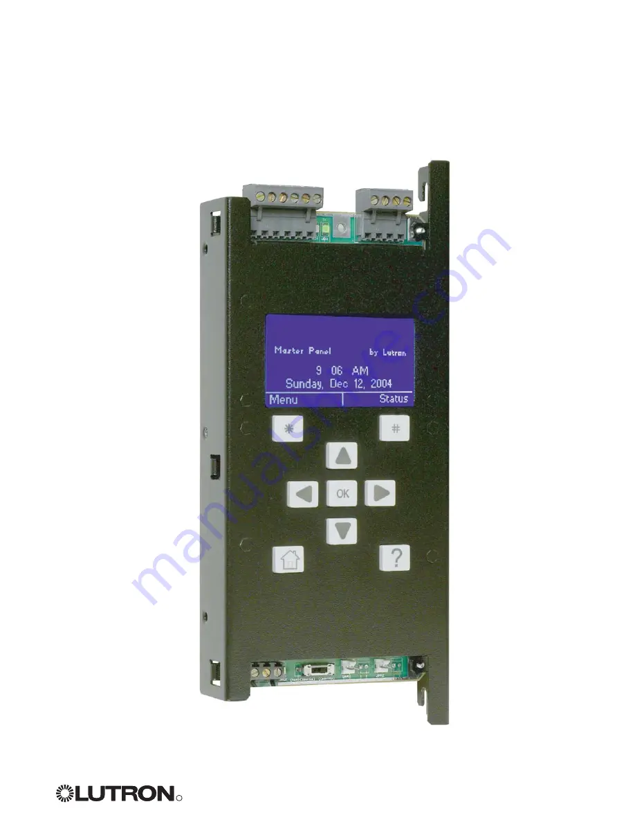
Page 9: ...ctor Panel Contact Closure Inputs Connector Digital Link Receive RX LED Digital Link Transmit TX LED 24 VAC Power Input Connector Normal Emergency Switch Module Control Harness Connectors Help Button...
Page 10: ...reen All screens on the LCP128 controller have a similar look with some common elements These are A screen title Left and right soft button labels A scroll bar only present if more information is avai...
Page 11: ...ing provides help on that item To go back to the previous screen press Back OK Entering Data One or more screens are used to program the information required for each system feature If only one screen...
Page 12: ...nlocking the Controller If the controller has been locked see Locking the Controller in the referenced function section you are prompted to enter the password before the Main Menu is activated Press a...
Page 13: ...t 6 07PM Time Clock Enabled Back Link Detail The Wallstation Status Screen Pressing from the Panel Status screen displays the Wallstation Status screen The Wallstation Status screen shows If the stati...
Page 14: ...ote wallstation key switch contact closure device and or RS232 device This step is performed to configure their function 5 Time Clock Events Required if the time clock will be used This step is used t...
Page 15: ...s only one panel you do not need to set the panel configuration The panel address first system circuit number and number of circuits are preprogrammed However for multi panel systems you must set the...
Page 16: ...e Language Cancel Done C Set System Size You can set the system size so that controller screens display only the circuits used by your system The default system size is 128 circuits A From the Main Me...
Page 17: ...uit number in the panel and press or Next E Use and to set the number of circuits in the panel and press or Done to update the database F Repeat this procedure at each remote panel to set the panel ad...
Page 18: ...ule type Module type options include X Four Circuit Switching Relay Module XP S One output circuit Dimming Module 1U D Two output circuit Dimming Module 2U Q Four output circuit Dimming Module 4U E Fo...
Page 19: ...V DALI PWM Dimming Incandescent MLV Magnetic Low Voltage Tu Wire ballasts Neon ELV Electronic Low Voltage Non dim DSI 0 10V DALI PWM Motors Motor Fans Fan N No ot te e Switching or dimming modules con...
Page 20: ...to highlight Load Setup and press or OK C Use and to highlight High End Trim Setup or Low End Trim Setup and press or OK D For each dimming circuit use and to select the circuit and and to set the tri...
Page 21: ...m 10 to 60 in 1 increments A From the Main Menu use and to highlight Panel Setup and press or OK B Use and to highlight Load Setup and press or OK C Use and to highlight Chicago Setup and press or OK...
Page 22: ...e to sunrise or sunset It is important to configure the time clock as needed for your location Time clock configuration includes Selecting a time format 12 or 24 hour Setting the time Setting the date...
Page 23: ...s or OK B Use and to change the current time Use and to alternate between hours and minutes C Press or Done to save changes OK OK Date A From the Setup Clock menu use and to highlight Date and press o...
Page 24: ...t Set Country USA Austria Belgium China Cancel Next Specify Latitude Longitude Latitude Longitude 9 6 N 075 1 W DEGREES DEGREES Cancel Next 3 C C D If Setting by Country and City C Use and to select t...
Page 25: ...rise or sunset time for your location by a fixed amount This can also be used to shift all time clock events that are relative to sunrise and sunset after they have been programmed If no offset is req...
Page 26: ...e United States rules for daylight savings time Starts on the 1st Sunday in April ends on the last Sunday in October at 2 AM offset by 1 hour then select United States Otherwise select Other Press or...
Page 27: ...ain dimming circuit levels rise and additional circuits turn on You can also assign scenes to control station inputs wallstation buttons key switches and contact closures This way any time a button is...
Page 28: ...ne press or Next D The Select CCO Address screen is displayed only if control station devices with contact closure outputs OMX AV or OMX CCO 8 have been entered into the system see STEP 4 Use and to s...
Page 29: ...ircuits are progressively lowered as long as input is received from the control station for example the button is held down key is turned contact closure is maintained Circuits stay at this setting un...
Page 30: ...t the Number of buttons and press or Next Note Do not count raise lower buttons F Use and to select the Button you want to program and press or Next G Use and to select the type of Action for this but...
Page 31: ...r on Circuit settings depend on the circuit type Switching ON OFF unaffected Dimming OFF 1 100 unaffected Motors Open Close Stop Jog Up Jog Down Fans Low Medium Medium High High Note The unaffected se...
Page 32: ...me Time to Off 10 min Previous Next H Assign Circuits PRESS OK TO SELECT CIRCUIT A L L C i r c u i ts 0 0 1 0 0 2 0 0 3 0 0 4 0 0 5 0 0 6 0 0 7 0 0 8 Previous Done I If Selecting a Lower Circuits Rais...
Page 33: ...and to select the type of Action for this key turn Lower Circuits Raise Circuits Scene Custom Scene Enable Time Clock Disable Time Clock Delay to Off Toggle and No Action and press or Next Refer to t...
Page 34: ...t closes and press or Next Note If there should be an action on both first set up the Open Action then follow this procedure again but choose Closure Action F Use and to select the type of Action for...
Page 35: ...the commands in that document work with the LCP128 system and they are listed below Command LCP128 Function Fade to Level Sets a pattern or time delay to off Multilevel Flash circuits Get Level Reque...
Page 36: ...ccupant a chance to press a button to keep lights on length of time is programmed as Off Delay Finally if a button has not been pressed lights turn off automatically at the end of the delay period If...
Page 37: ...or offset Adjust the time using and and press or Next F Use and to select the desired Action for the event Scene Custom Scene Enable or Disable Controls Afterhours Start or Afterhours End and press or...
Page 38: ...levels to be used for afterhours mode Then press or Done Refer to the beginning of STEP 5 for a detailed description of how afterhours mode works To add another event to this same schedule select Yes...
Page 39: ...nd lasting 2 days Dec 31 and Jan 1 E Use and to select Fixed Time or at a time relative to Sunset or Sunrise Press to adjust the time or offset Adjust the time using and and press or Next F Use and to...
Page 40: ...paste the event to another day or holiday select Yes when prompted to Paste Again OK OK OK OK OK OK Select Event to Copy Sun All Events Sun Fixed 08 00 AM Sun Sunrise 0 15 Sun Sunset 0 30 Previous Nex...
Page 41: ...ation Setup Panel CCI Setup Scene Setup Panel Setup Back OK Viewing Modifying Events A From the Main Menu use and to highlight Time Clock Setup and press or OK B Use and to highlight View Modify Event...
Page 42: ...e input is activated the assigned circuits toggle between on and off If the assigned circuits are in a mixed state some on and some off the circuits turn on Delay To Off Each time the contact closure...
Page 43: ...Time Clock Delay to Off Toggle or No Action Program the desired action using the following procedures OK OK OK Panel 1 CCI 1 Open Action Closure Action Previous Next 001 E C Panel CCI Setup Panel 1 CC...
Page 44: ...on Circuit settings depend on the circuit type Switching ON OFF unaffected Dimming OFF 1 100 unaffected Motors Raise Lower Stop Jog Up Jog Down Fans Low Medium Medium High High Note The unaffected set...
Page 45: ...mber and press to toggle between Assigned and Unassigned dashed All circuits can be toggled by selecting ALL Circuits and pressing When the circuits are programmed press G For dimming circuits affecte...
Page 46: ...t the emergency panel will go to the emergency settings factory set to all circuits On Notes If UL 924 certification is required the Lutron Emergency Lighting Interface LUT ELI 3PH may be used to meet...
Page 47: ...e The unaffected setting means the circuit is not affected by emergency mode When the circuits are programmed for emergency mode press or Next E The Select CCO Address screen is displayed only if cont...
Page 48: ...se call 800 523 9466 with any feedback or suggestions Thank you for your help Your LCP128 System is now programmed and ready to use Keep this guide with the system It should include the completed Cont...
Page 49: ...e Scene Override Directly apply circuit settings using a different scene The override occurs immediately and remains in effect as long as the Select Scene screen is displayed on the controller Pressin...
Page 50: ...e Flash setting cycles a circuit between On and Off once every few seconds useful for locating a circuit in the space Changes take effect immediately As long as the Set Circuit Levels screen is displa...
Page 51: ...s contact closure inputs and so on The override Select Scene screen will not time out to the Home screen or screen saver D To exit the Select Scene screen and keep the scene settings press or Done The...
Page 52: ...o Disabled or Enable and press or Done OK OK OK Time Clock Override Time Clock Events Cancel Done Enabled Control Stations Override Control Stations Cancel Done Overrides Set Circuit Levels Select Sce...
Page 53: ...or OK C Use and to select either Change Password or Set Lockout Time and press or OK D If Set Lockout Time is selected use and to set the time of inactivity no button presses on the controller to wait...
Page 54: ...me screen You need to unlock the controller before you can access the Main Menu A Press Unlock B To enter the password use and to select the digit to change and then and to change each value When you...
Page 55: ...CP128 panel or in a separate distribution panel if the LCP128 is a feed through panel f Duplicate panel addresses f Check that all panel addresses are unique The panel address is listed on the Home sc...
Page 56: ...ons are disabled d Enable the control stations using the controller See the Overrides section in this guide for more information e Control station link is mis wired e See the LCP128 Installation Guide...
Page 57: ...es a Check that all panel addresses are unique The panel address is listed on the Home screen To change addresses see STEP 1 in this guide for more information b Duplicate control station addresses b...
Page 58: ...work a Sense lines are not connected a For emergency to work the right most pin on the 6 pin connector at the top of the controller must be wired between panels See the LCP128 Installation Guide for...
Page 59: ...ould be in the ON position b See Control station buttons do not work Symptom of this troubleshooting section OMX AV outputs are not working a DIP switch 8 on OMX AV is not set correctly a Set DIP swit...
Page 60: ...ts LCP128 Panels 1 Clean any dirt from air vent openings with a vacuum and check for any obstructions which may block air flow Keep 12 30 5 cm above and below panels unobstructed 2 If any extra wiring...
Page 61: ...ur on a holiday LCD Liquid Crystal Display the graphical display built into the LCP128 controller that is used to configure the system LED Light Emitting Diode an illuminated indicator to help in diag...
Page 62: ...uit System Circuit Description 1 2 3 4 5 6 7 8 9 10 11 12 13 14 15 16 17 18 19 20 21 22 23 24 25 26 27 28 29 30 31 32 33 34 35 36 Panel 2 Panel Circuit System Circuit Description How to Use These Tabl...
Page 63: ...nel Circuit System Circuit Description 1 2 3 4 5 6 7 8 9 10 11 12 13 14 15 16 17 18 19 20 21 22 23 24 25 26 27 28 29 30 31 32 33 34 35 36 Panel 4 Panel Circuit System Circuit Description How to Use Th...
Page 64: ...11 12 13 14 15 16 17 18 19 20 21 22 23 24 25 26 27 28 29 30 31 32 33 34 35 36 Panel 5 Panel Circuit System Circuit Description 1 2 3 4 5 6 7 8 9 10 11 12 13 14 15 16 17 18 19 20 21 22 23 24 25 26 27...
Page 65: ...11 12 13 14 15 16 17 18 19 20 21 22 23 24 25 26 27 28 29 30 31 32 33 34 35 36 Panel 7 Panel Circuit System Circuit Description 1 2 3 4 5 6 7 8 9 10 11 12 13 14 15 16 17 18 19 20 21 22 23 24 25 26 27...
Page 66: ...28 panel in the system indicates the quantity and type of modules present in that panel Example Model Number LCP 2S4Q 1204ML 20 Panel with two 1 output dimming modules 2S and four 4 output dimming mod...
Page 67: ...fluorescent lamps equipped with Lutron Tu Wire dimming ballasts For use with electronic transformer low voltage lighting Requires Lutron ELVI 1000 external interface Non Dim For use with electronic tr...
Page 68: ...on Table 1 2 3 4 5 6 7 8 9 10 11 12 13 14 15 16 17 18 19 20 21 22 23 24 25 26 27 28 29 30 31 32 Address Number of Buttons Location Description How to Use This Table For each control station fill in th...
Page 69: ...4 15 16 17 18 19 20 21 22 23 24 1 2 3 4 5 6 7 8 9 10 11 12 13 14 15 16 17 18 19 20 21 22 23 24 Address Location Description Control Station Button Kitchen Janitor s Closet 8 0 8 0 Action Sample System...
Page 70: ...3 44 45 46 47 48 49 50 51 52 53 54 55 56 57 58 59 60 61 62 63 64 25 26 27 28 29 30 31 32 33 34 35 36 37 38 39 40 41 42 43 44 45 46 47 48 49 50 51 52 53 54 55 56 57 58 59 60 61 62 63 64 System Circuit...
Page 71: ...day and time of each time clock event For each event record the action and which circuits are affected Time Action Fixed Sunrise Sunset Time Day Holiday Scene or Custom Scene Afterhours Start Afterhou...
Page 72: ...e other rights which vary from state to state Some states do not allow limitations on how long an implied warranty lasts so the above limitation may not apply to you Some states do not allow the exclu...