background image

7 | 

P a g e


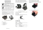
To the right will be options to configure the Program Type, Button Type, and LED Logic. As a 
result of the buttons not having LED status indication, buttons are typically programmed as 
Single Action with Scene LED logic. The buttons can be assigned any Program Type (Normal, 
Single Variable, or Conditional) and can be program to control any Assignable Item in the 
database. 


Note:

 Make sure that the proper button mapping is being followed in order to assign the 

appropriate actions to Sleeve Buttons. The orientation of the Sleeve Buttons on the wall will 
determine the button mapping in the programming software. See section 

Appendix A 

in 

Section 7.0


2.4    Programming LaunchPort Sleeve Buttons to Control 3

rd

 Party 

Equipment 


The LaunchPort Sleeve Buttons can be configured to control 3

rd

 party equipment as well as 

Lutron products. There are two ways to typically accomplish this: send outbound strings of 
communication to the 3

rd

 party devices using the Control 3

rd

 Party feature of the HomeWorks 

QS software or by using Lutron’s Integration Protocol to allow the 3

rd

 party system to understand 

Lutron system commands. Many 3

rd

 party manufacturers have drivers already written to allow 

easier integration between Lutron and their system. 

In either case, the HomeWorks QS Processor would connect into the Local Area Network that 
the 3

rd

 party equipment is connected to. If the 3

rd

 party equipment communicates primarily via 

RS-232 serial communication, a serial to Ethernet converter is recommended to allow the 3

rd


party system to communicate into the Local Area Network. 

There are two primary ways in which the buttons could activate functions in the 3

rd

 party system. 

One way would be to send a command, built into the database via a Control 3

rd

 Party device. 

Summary of Contents for launchport am.2

Page 1: ...mount and charge an iPad anywhere in the residence There are versions of the AM 2 which contain Clear Connect RF technology from Lutron allowing seamless integration with Lutron Systems via 5 program...

Page 2: ...ogramming LaunchPort Sleeve Buttons to Control a RadioRA 2 System 11 3 4 Programming LaunchPort Sleeve Buttons to Control 3rd Party Equipment 13 3 5 Activating LaunchPort Sleeve Buttons to a RadioRA 2...

Page 3: ...ve Buttons to the HomeWorks QS System 2 1 1 Wireless RF Link Connection In this configuration the LaunchPort Sleeve Buttons communicate to the HomeWorks QS processor by sending wireless data to a Hybr...

Page 4: ...addressed to a single QSM HQP6 2 HWQS Processor QSM2 XW QS Sensor Module QS Wired Link LaunchPort Sleeve Buttons w iPad Home Control app 2 2 Adding LaunchPort Sleeve Buttons to a HomeWorks QS Database...

Page 5: ...via the RF Link as shown in Section 2 1 1 the Pico placeholder must be link assigned to the appropriate RF link Go to Design Link Assignment to associate the Pico If the Sleeve Buttons are going to c...

Page 6: ...o 3BRL placeholder added in Section 2 2 Go to Program Devices Use the Device Location drop down menu to select the area where the Pico 3BRL has been placed and click on the Pico 3BRL image to select t...

Page 7: ...ontrol 3rd party equipment as well as Lutron products There are two ways to typically accomplish this send outbound strings of communication to the 3rd party devices using the Control 3rd Party featur...

Page 8: ...amming software Refer to the application note titled Integration with Ethernet and RS 232 Devices for further information This application note can be found on the HomeWorks QS Resource site under Tec...

Page 9: ...ater connected to the Main Repeater Up to 4 Auxiliary Repeaters can be utilized per Main Repeater with a maximum of 2 Main Repeaters allowed per RadioRA 2 system Each Main Repeater can support up to 9...

Page 10: ...the Sleeve Buttons will be installed by clicking on the room name within the room list Click on the to add a new Device Location within the room Click on the image of the Pico Wireless Controller with...

Page 11: ...hosen and that no unnecessary additional gear will be added to the Bill of Materials Click on Done in the lower right corner of the Add New Device window to finish adding the Pico placeholder to the d...

Page 12: ...ill be a drop down menu to select a room This drop down menu is used to locate the zones that you would like the Pico button to control In order to allow the programming of lights and shades to the sa...

Page 13: ...ng LaunchPort Sleeve Buttons to Control 3rd Party Equipment The LaunchPort Sleeve Buttons can be configured to control 3rd party equipment as well as Lutron products by using Lutron s Integration Prot...

Page 14: ...n Report built into the programming software On an installation which does require LaunchPort Sleeve Buttons functionality but does not currently require Lutron product a Main Repeater and one device...

Page 15: ...ta Wireless dimmers switches and window treatment solutions For more information on non Smart Bridge setup refer to Section 6 0 LaunchPort Sleeve Buttons w iPad Cas ta Wireless Smart Bridge 4 2 Assoc...

Page 16: ...ote from the Add Device screen Once the Pico Remote has been chosen the app will show how to add a Pico Remote to the Smart Bridge Ensure that the proper Sleeve Button is being pressed and held For mo...

Page 17: ...eeve Buttons can communicate directly with a Grafik Eye QS Mimicking a 3 Button w Raise and Lower Pico Wireless Controller the LaunchPort Sleeve Buttons can control lights and shades tied to the Grafi...

Page 18: ...uct Specification Submittal for more details on the hardware and wiring specifications 5 1 2 Wired QS Link Connection In this configuration the LaunchPort Sleeve Buttons communicate to the Grafik Eye...

Page 19: ...QS For Sleeve Buttons oriented to the right of the iPad the top button will control Scene 1 the center button will control Scene 16 and the bottom button will control the Off Scene If zone is chosen...

Page 20: ...Cas ta Wireless dimmers RadioRA 2 dimmers HomeWorks QS dimmers In these applications the Clear Connect wireless communication is direct from the transmitter to the dimmer or shade The association and...

Page 21: ...em as the button mapping changes in relation to the sleeve button position Below is the button topology of a PJ2 3BRL and serves as a legend to the table and image below which illustrate the appropria...

Page 22: ...n any of the 15 available channels the LaunchPort Sleeve Buttons cannot receive or listen to these commands and must be forced to a different frequency For more information on these processes in a Hom...

Page 23: ...ns The icons and texts can be correlated through software to the appropriate intuitive function The five icons used by default are numbered 1 through 5 Below are the 30 alternative options Example app...

Reviews: