


5
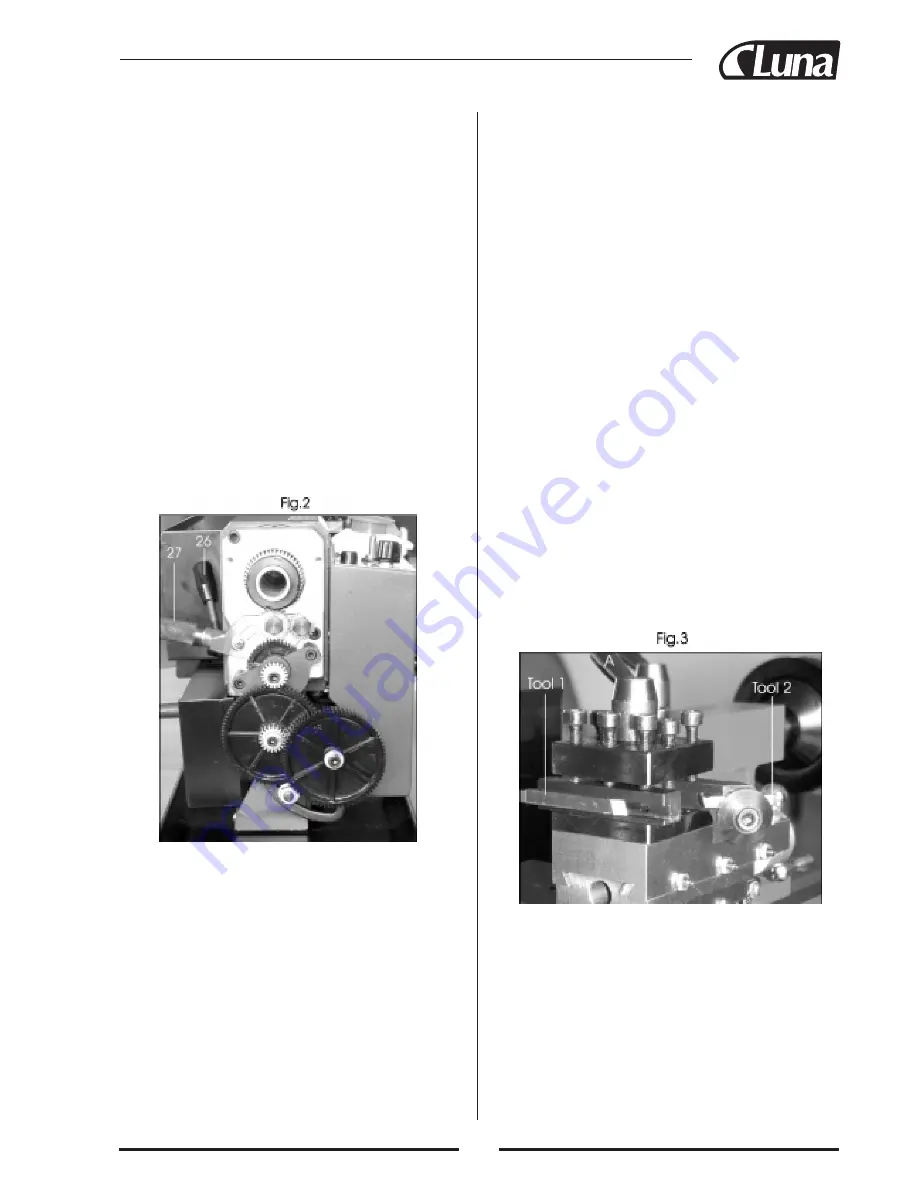
The gear train, shown in Fig. 2, transmits drive to the Lead
screw. The lead Screw acts as a worm and by Operating the
Auto Feed lever (15), which engages a nut with the lead
screw, drive is transmitted to the carriage/saddle and conse-
quently the cutting tool. There-by providing a power feed
for thread cutting or general turning operations. The rotatio-
nal speed of the lead screw, and hence the rate of feed of the
cutting tool, is determined by the gear configuration. This is
explained in greater detail under “Screw cutting”.
The drive to the lead screw may be disconnected by opera-
ting the lever (27). And the same lever is used to drive the
lead screw in a forward or reverse direction. (These actions
are described in detail under (WScrew cutting”.)
3. THE TAILSTOCK
The tailstock (9), may be moved along the bed to any des-
ired position and is secured in position by a single nut (10),
at its bade. The tailstock spindle carries an internal No. 2
Morse taper for use with the Center provided. A Revolving
Live Center and Drill Chuck are also available from your
dealer. (See Accessories.)
4. THE CARRIAGE / SADDLE
The Saddle carries the Cross-Slide (6) onto which is moun-
ted the Compound Slide (7) with Tool post (5), allowing
intricate and delicate operations to be performed. It may be
driven by the Lead screw, via a driver nut, to provide auto-
matic feed when the Auto Feed lever (15), mounted on the
Apron (17), is operated.
The position of the tool is effected by turning the cross 0/-
slide feed handle (16), which moves it across the lathe, and
the carriage/saddle or manual feed handle (18), which
moves it longitudinally. Additionally the compound slide
feed handle (13) may be used to move the tool by small
amounts at right angles to the cross-slide. The slide may be
set at an angle to the cross-slide so that short tapers or bevels
may be cut. This is described in greater detail under “Bevel
Cutting”.
The cross-slide and compound slide feeds are provided with
a scale. These are used to move the tool by precise amounts
– one division being equivalent to 0.001” (0.025 mm). As
the feed handle is turned. So does the scale. The scale on the
cross-slide feed may also be held stationary whilst the hand-
le is turned. Allowing the scale to be “zeroed”. The manner
in which this is put to use is discussed in greater detail under
“Operation”.
The tool post carries 8 hex socket head screws which are
used to secure a cutting tool in any desired position. Four
tool bits may be mounted for quick and easy changes. Two
are shown mounted.
The tool post is rotated by slackening the lever (A) on its top
a sufficient amount so the post can be lifted slightly and then
turned to the desired position
ALWAYS be ensure the post, and hence the tool, is secured
by tighten the lever firmly before attempting to cut.
5. THE MOTOR
Disassembly of the motor is not recommended. Brushes
1. THE HEADSTOCK
The motor provides a direct drive to the spindle via an inter-
nal tooth type belt. Spindle speed is variable, and is regula-
ted by the Speed Control Knob (23). Located on the main
control panel.
The spindle, is provided with an internal No. 3 Morse taper
to accommodate a center for use with a face plate or turning
clamp.
The 3-jaw self centering chuck (4) is mounted on the spind-
le flange (2). To remove the chuck, simply remove the three
securing nuts to rear of the flange allowing it to be pulled
free together with the three mounting studs.
Three external jaws are also supplied which extend the
capacity of the chuck. Their uses and method of assembly is
described under “Accessories”.
The spindle has 6 holes drilled in its flange to accommoda-
te a range of fixtures such as d Face plate. 4-jaw chuck etc.
(See Accessories.)
2. THE RUNNING GEAR
The Running Gear is protected by a cover (22), which is
removed by unscrewing the two securing hex. Screws.


